SECTION 5 − OPERATION
5-1. Controls
2
3 | 6 |
|
5
4 | 7 | 1 |
229
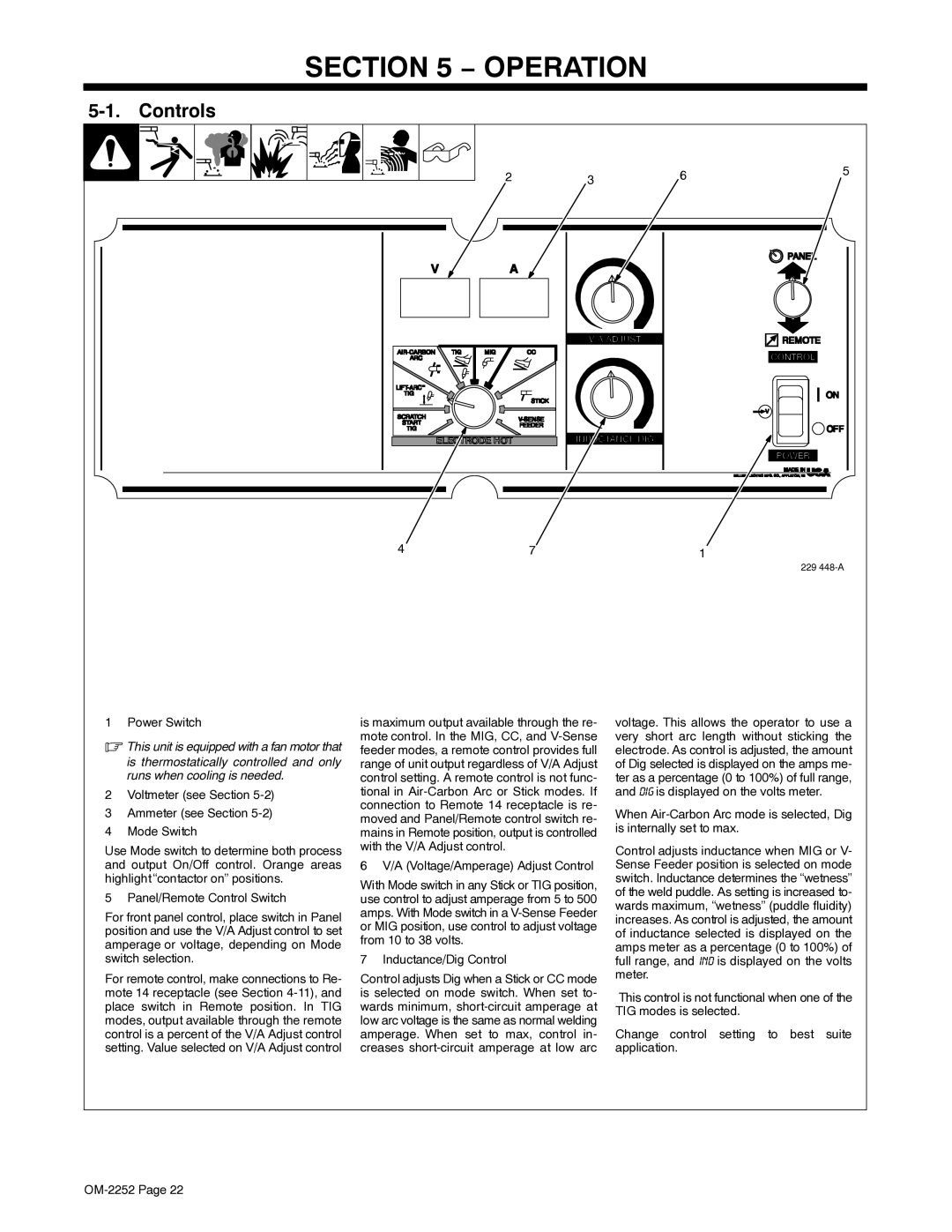
1 Power Switch
.This unit is equipped with a fan motor that
is thermostatically controlled and only runs when cooling is needed.
2Voltmeter (see Section 5-2)
3Ammeter (see Section 5-2)
4Mode Switch
Use Mode switch to determine both process and output On/Off control. Orange areas highlight “contactor on” positions.
5 Panel/Remote Control Switch
For front panel control, place switch in Panel position and use the V/A Adjust control to set amperage or voltage, depending on Mode switch selection.
For remote control, make connections to Re- mote 14 receptacle (see Section
is maximum output available through the re- mote control. In the MIG, CC, and
6 V/A (Voltage/Amperage) Adjust Control
With Mode switch in any Stick or TIG position, use control to adjust amperage from 5 to 500 amps. With Mode switch in a
7 Inductance/Dig Control
Control adjusts Dig when a Stick or CC mode is selected on mode switch. When set to- wards minimum,
voltage. This allows the operator to use a very short arc length without sticking the electrode. As control is adjusted, the amount of Dig selected is displayed on the amps me- ter as a percentage (0 to 100%) of full range, and dig is displayed on the volts meter.
When
Control adjusts inductance when MIG or V- Sense Feeder position is selected on mode switch. Inductance determines the “wetness” of the weld puddle. As setting is increased to- wards maximum, “wetness” (puddle fluidity) increases. As control is adjusted, the amount of inductance selected is displayed on the amps meter as a percentage (0 to 100%) of full range, and ind is displayed on the volts meter.
This control is not functional when one of the TIG modes is selected.
Change control setting to best suite application.