3-9. Installing Drive Rolls and Wire Guide
3
2
1
4
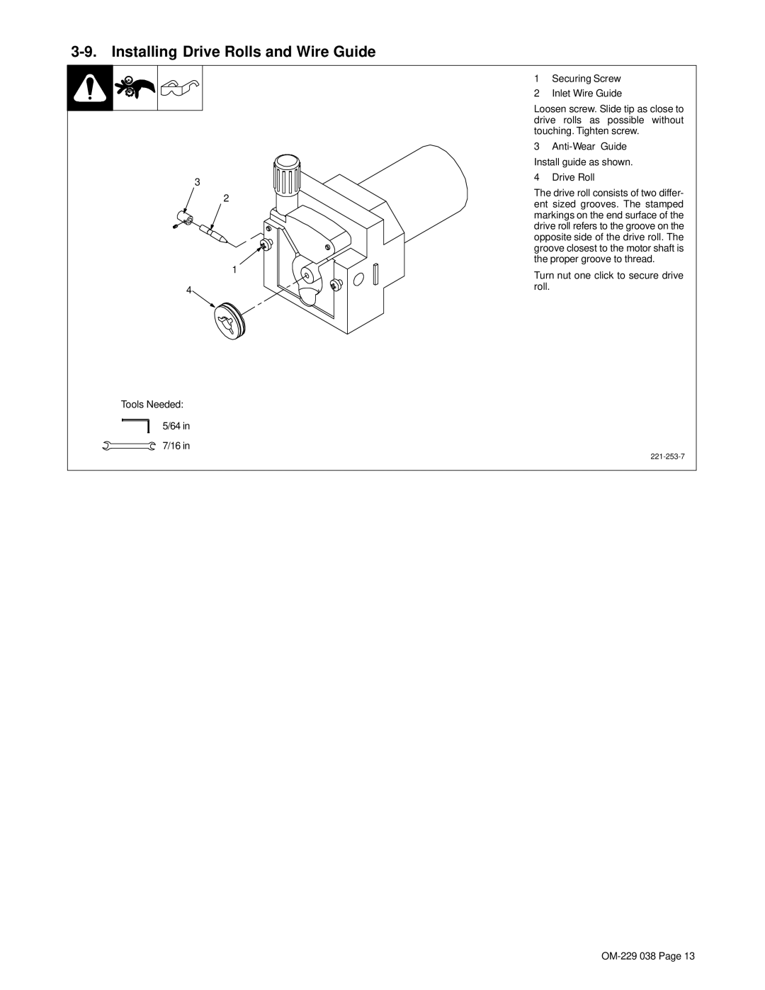
Tools Needed:
5/64 in
7/16 in
1Securing Screw
2Inlet Wire Guide
Loosen screw. Slide tip as close to drive rolls as possible without touching. Tighten screw.
3
4Drive Roll
The drive roll consists of two differ- ent sized grooves. The stamped markings on the end surface of the drive roll refers to the groove on the opposite side of the drive roll. The groove closest to the motor shaft is the proper groove to thread.
Turn nut one click to secure drive roll.