5-7. Feeder Set Up Push Button
3
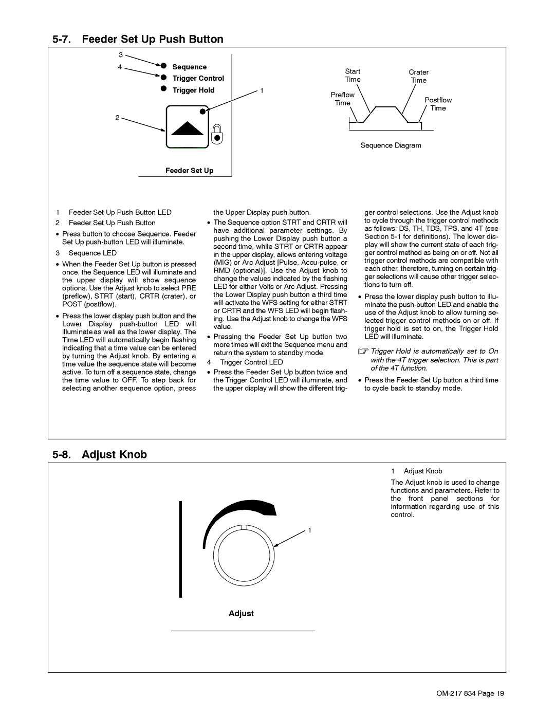
4


 Sequence
Trigger Control
Trigger Hold
2
Feeder Set Up
| Start | Crater | ||
| Time | Time | ||
1 | Preflow |
|
| |
| Postflow | |||
| Time | |||
| Time | |||
|
|
| ||
|
|
|
| |
|
|
|
| |
|
| Sequence Diagram | ||
1Feeder Set Up Push Button LED
2Feeder Set Up Push Button
•Press button to choose Sequence. Feeder Set Up
3 Sequence LED
•When the Feeder Set Up button is pressed once, the Sequence LED will illuminate and the upper display will show sequence options. Use the Adjust knob to select PRE (preflow), STRT (start), CRTR (crater), or POST (postflow).
•Press the lower display push button and the Lower Display
the Upper Display push button.
•The Sequence option STRT and CRTR will have additional parameter settings. By pushing the Lower Display push button a second time, while STRT or CRTR appear in the upper display, allows entering voltage (MIG) or Arc Adjust [Pulse,
•Pressing the Feeder Set Up button two more times will exit the Sequence menu and return the system to standby mode.
4 Trigger Control LED
•Press the Feeder Set Up button twice and the Trigger Control LED will illuminate, and the upper display will show the different trig-
ger control selections. Use the Adjust knob to cycle through the trigger control methods as follows: DS, TH, TDS, TPS, and 4T (see Section
•Press the lower display push button to illu- minate the
.Trigger Hold is automatically set to On
with the 4T trigger selection. This is part of the 4T function.
•Press the Feeder Set Up button a third time to cycle back to standby mode.
5-8. Adjust Knob
1 Adjust Knob
The Adjust knob is used to change functions and parameters. Refer to the front panel sections for information regarding use of this control.
1
Adjust