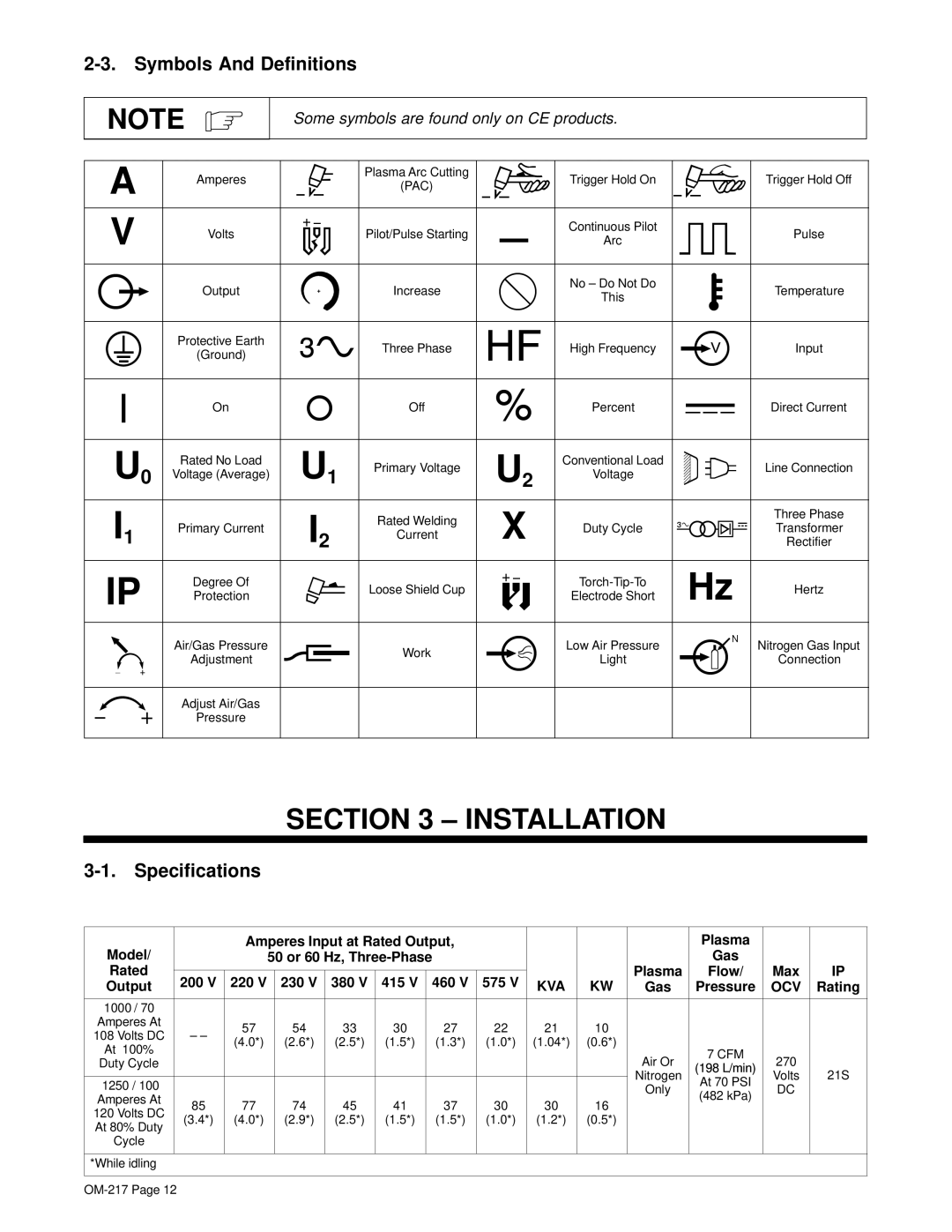
Spectrum 1000, Spectrum 1250R specifications
Miller Electric has long been a leader in advanced welding technology, and the Spectrum 1250R and Spectrum 1000 are prime examples of their revolutionary products designed for professionals. Both models are plasma cutting systems that offer remarkable performance, durability, and user-friendly features tailored for precision cutting in various applications.The Spectrum 1250R is known for its robust capabilities, boasting a maximum cutting thickness of up to 1 inch on mild steel. Its powerful 125 amp output ensures rapid cutting while maintaining a clean edge, which is essential for industries requiring precision and efficiency. The integrated Auto-Refire technology minimizes downtime by enabling the torch to continue cutting even through brief interruptions. Users appreciate the system’s portability, thanks to its lightweight design and convenient shoulder strap.
The Spectrum 1000, while slightly less powerful, is no less impressive. It supports a maximum cutting thickness of ¾ of an inch on mild steel, making itideal for medium-scale projects and applications. Its advanced technologies include an Easy Start feature that guarantees quick arc initiation without the need for high-frequency start options. This is particularly beneficial in reducing the risk of damaging sensitive electronics nearby.
Both models incorporate Miller’s Auto-Set technology, which streamlines operations by automatically adjusting the settings to match the material thickness and type. This innovative feature eliminates the guesswork for users, allowing for consistent results and enhancing overall productivity. The systems also utilize a unique drag-cutting capability, enabling users to maintain the torch directly on the workpiece for improved cut quality and control.
Moreover, the durability of the Spectrum series is highlighted by their seal design that protects critical internal components from dust and contaminants, significantly extending the lifespan of the units. Adjustments and maintenance are simplified, thanks to the easy-access design of the consumables.
In terms of safety, both models prioritize user protection, featuring thermal and overload protection to prevent overheating and prolonging the life of the equipment. Whether being utilized in a workshop or an outdoor environment, the Spectrum 1250R and Spectrum 1000 provide reliable, high-quality performance desired by welding professionals. Their combination of cutting-edge technology, ease of use, and robust design makes them invaluable tools in the toolbox of any welder or metalworker.

