DANGER To avoid electrical shock: Never make measurement on a circuit in which voltage over 600V AC/DC exists.
Do not use with the Battery Cover removed. Keep fingers behind the guards and away from test lead tips during measurements.
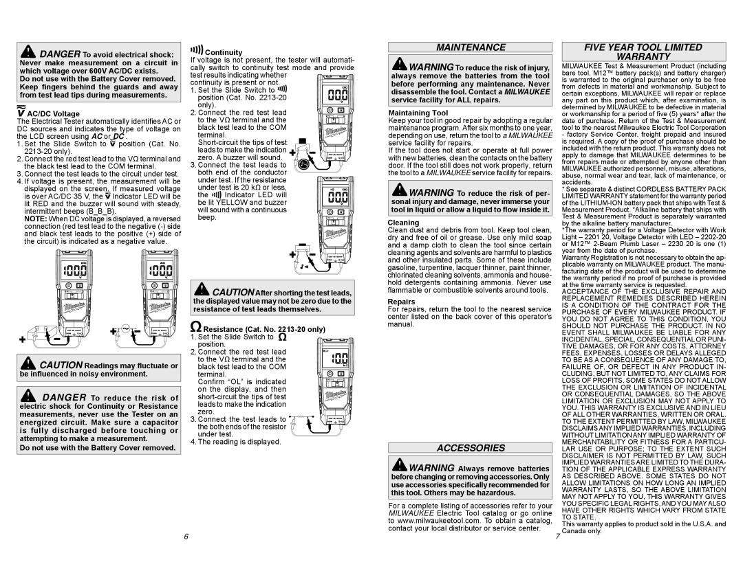
AC/DC Voltage
The Electrical Tester automatically identifies AC or DC sources and indicates the type of voltage on the LCD screen using AC or DC .
1.Set the Slide Switch to  position (Cat. No. 2213-20 only).
2.Connect the red test lead to the VΩ terminal and the black test lead to the COM terminal.
3.Connect the test leads to the circuit under test.
4.If voltage is present, the measurement will be displayed on the screen. If measured voltage is over AC/DC 35 V, the  Indicator LED will be lit RED and the buzzer will sound with steady, intermittent beeps (B_B_B).
NOTE: When DC voltage is displayed, a reversed connection (red test lead to the negative (-) side and black test leads to the positive (+) side of
the circuit) is indicatedġas a negative value.
CAUTION Readings may fluctuate or be influenced in noisy environment.
DANGER To reduce the risk of electric shock for Continuity or Resistance measurements, never use the Tester on an energized circuit. Make sure a capacitor is fully discharged before touching or attempting to make a measurement.
Do not use with the Battery Cover removed.


 Continuity
If voltage is not present, the tester will automati-
cally switch to continuity test mode and provide |
test results indicating whether |
continuity is present or not. |
1. Set the Slide Switch to |
position (Cat. No. 2213-20 |
only). | |
2. Connect the red test lead |
to the VΩ terminal and the |
black test lead to the COM |
terminal. |
Short-circuit the tips of test |
leads to make the indication |
zero. A buzzer will sound. |
3. Connect the test leads to |
both end of the conductor |
under test. If the resistance |
under test is 20 kΩ or less, |
the | Indicator LED will |
be lit YELLOW and buzzer |
will sound with a continuous |
beep. | |
 CAUTION After shorting the test leads, the displayed value may not be zero due to the resistance of test leads themselves.
 Resistance (Cat. No. 2213-20 only)
1. Set the Slide Switch to position.
2. Connect the red test lead to the VΩ terminal and the black test lead to the COM terminal. Confirm “OL” is indicated on the display, and then short-circuit the tips of test leads to make the indication zero.
3. Connect the test leads to 


 the both ends of the resistor


 under test.
4. The reading is displayed.
6
MAINTENANCE
 WARNING To reduce the risk of injury, always remove the batteries from the tool before performing any maintenance. Never disassemble the tool. Contact a MILWAUKEE service facility for ALL repairs.
Maintaining Tool
Keep your tool in good repair by adopting a regular maintenance program. After six months to one year, depending on use, return the tool to a MILWAUKEE service facility for repairs.
If the tool does not start or operate at full power with new batteries, clean the contacts on the battery door. If the tool still does not work properly, return the tool to a MILWAUKEE service facility for repairs.
 WARNING To reduce the risk of per- sonal injury and damage, never immerse your tool in liquid or allow a liquid to flow inside it.
Cleaning
Clean dust and debris from tool. Keep tool clean, dry and free of oil or grease. Use only mild soap and a damp cloth to clean the tool since certain cleaning agents and solvents are harmful to plastics and other insulated parts. Some of these include gasoline, turpentine, lacquer thinner, paint thinner, chlorinated cleaning solvents, ammonia and house- hold detergents containing ammonia. Never use flammable or combustible solvents around tools.
Repairs
For repairs, return the tool to the nearest service center listed on the back cover of this operator's manual.
ACCESSORIES
 WARNING Always remove batteries before changing or removing accessories. Only use accessories specifically recommended for this tool. Others may be hazardous.
For a complete listing of accessories refer to your MILWAUKEE Electric Tool catalog or go online to www.milwaukeetool.com. To obtain a catalog, contact your local distributor or service center.
FIVE YEAR TOOL LIMITED
WARRANTY
MILWAUKEE Test & Measurement Product (including bare tool, M12™ battery pack(s) and battery charger) is warranted to the original purchaser only to be free from defects in material and workmanship. Subject to certain exceptions, MILWAUKEE will repair or replace any part on this product which, after examination, is determined by MILWAUKEE to be defective in material or workmanship for a period of five (5) years* after the date of purchase. Return of the Test & Measurement tool to the nearest Milwaukee Electric Tool Corporation
-factory Service Center, freight prepaid and insured is required. A copy of the proof of purchase should be included with the return product. This warranty does not apply to damage that MILWAUKEE determines to be from repairs made or attempted by anyone other than MILWAUKEE authorized personnel, misuse, alterations, abuse, normal wear and tear, lack of maintenance, or accidents.
* See separate & distinct CORDLESS BATTERY PACK LIMITED WARRANTY statement for the warranty period of the LITHIUM-ION battery pack that ships with Test & Measurement Product. *Alkaline battery that ships with Test & Measurement Product is separately warranted by the alkaline battery manufacturer.
*The warranty period for a Voltage Detector with Work Light – 2201 20, Voltage Detector with LED – 2202-20 or M12™ 2-Beam Plumb Laser – 2230 20 is one (1) year from the date of purchase.
Warranty Registration is not necessary to obtain the ap- plicable warranty on MILWAUKEE product. The manu- facturing date of the product will be used to determine the warranty period if no proof of purchase is provided at the time warranty service is requested.
ACCEPTANCE OF THE EXCLUSIVE REPAIR AND REPLACEMENT REMEDIES DESCRIBED HEREIN IS A CONDITION OF THE CONTRACT FOR THE PURCHASE OF EVERY MILWAUKEE PRODUCT. IF YOU DO NOT AGREE TO THIS CONDITION, YOU SHOULD NOT PURCHASE THE PRODUCT. IN NO EVENT SHALL MILWAUKEE BE LIABLE FOR ANY INCIDENTAL, SPECIAL, CONSEQUENTIAL OR PUNI- TIVE DAMAGES, OR FOR ANY COSTS, ATTORNEY FEES, EXPENSES, LOSSES OR DELAYS ALLEGED TO BE AS A CONSEQUENCE OF ANY DAMAGE TO, FAILURE OF, OR DEFECT IN ANY PRODUCT IN- CLUDING, BUT NOT LIMITED TO, ANY CLAIMS FOR LOSS OF PROFITS. SOME STATES DO NOT ALLOW THE EXCLUSION OR LIMITATION OF INCIDENTAL OR CONSEQUENTIAL DAMAGES, SO THE ABOVE LIMITATION OR EXCLUSION MAY NOT APPLY TO YOU. THIS WARRANTY IS EXCLUSIVE AND IN LIEU OF ALL OTHER WARRANTIES, WRITTEN OR ORAL. TO THE EXTENT PERMITTED BY LAW, MILWAUKEE DISCLAIMS ANY IMPLIED WARRANTIES, INCLUDING WITHOUT LIMITATION ANY IMPLIED WARRANTY OF MERCHANTABILITY OR FITNESS FOR A PARTICU- LAR USE OR PURPOSE; TO THE EXTENT SUCH DISCLAIMER IS NOT PERMITTED BY LAW, SUCH IMPLIED WARRANTIES ARE LIMITED TO THE DURA- TION OF THE APPLICABLE EXPRESS WARRANTY AS DESCRIBED ABOVE. SOME STATES DO NOT ALLOW LIMITATIONS ON HOW LONG AN IMPLIED WARRANTY LASTS, SO THE ABOVE LIMITATION MAY NOT APPLY TO YOU, THIS WARRANTY GIVES YOU SPECIFIC LEGAL RIGHTS, AND YOU MAY ALSO HAVE OTHER RIGHTS WHICH VARY FROM STATE TO STATE.
This warranty applies to product sold in the U.S.A. and
7Canada only.