Reduced Kickback Guide Bar
A guide bar which has been demonstrated to reduce kickback significantly.
Replacement Saw Chain
A chain that complies with the kickback performance requirements of ANSI B175.1- 2000 when tested with specific chain saws. It may not meet the ANSI perfor- mance requirements when used with other saws.
Saw Chain
A loop of chain having cutting teeth, that cut the wood, and that is driven by the motor and is supported by the guide bar.
Spiked Bumper (Spike) (Fig. 6)
The pointed tooth or teeth (A)for use when felling or bucking to pivot the saw and maintain position while sawing.
Fig. 6
A
Switch Linkage
The mechanism that transmits motion from a trigger to the switch.
Switch (Fig. 7)
A device that when operated will complete or interrupt an electrical power circuit to the motor of the chain saw (A).
Fig. 7
B
A
Switch Lockout (Fig. 7)
A movable stop (B) that prevents the unin- tentional operation of the switch until manu- ally actuated.
TOOL ASSEMBLY
![]()
![]()
![]() WARNING!
WARNING!
To reduce the risk of injury, always unplug tool before per- forming any assembly, adjust- ments, maintenance or service.
Contact a MILWAUKEE service facility for ALL repairs. Use only
specifically recommended accessories. Others may be hazardous.
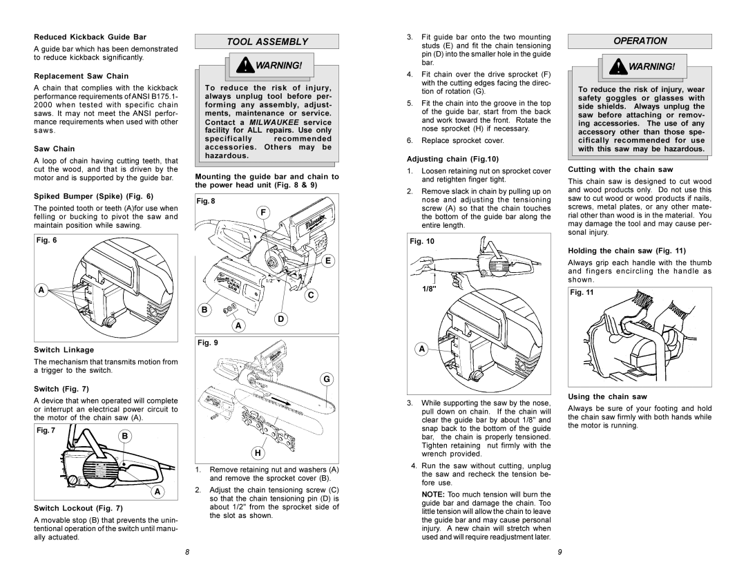
Mounting the guide bar and chain to the power head unit (Fig. 8 & 9)
Fig. 8
F
E
C
B
D
A
Fig. 9
G
H
1.Remove retaining nut and washers (A) and remove the sprocket cover (B).
2.Adjust the chain tensioning screw (C) so that the chain tensioning pin (D) is about 1/2" from the sprocket side of the slot as shown.
3.Fit guide bar onto the two mounting studs (E) and fit the chain tensioning pin (D) into the smaller hole in the guide bar.
4.Fit chain over the drive sprocket (F) with the cutting edges facing the direc- tion of rotation (G).
5.Fit the chain into the groove in the top of the guide bar, start from the back and work toward the front. Rotate the nose sprocket (H) if necessary.
6.Replace sprocket cover.
Adjusting chain (Fig.10)
1.Loosen retaining nut on sprocket cover and retighten finger tight.
2.Remove slack in chain by pulling up on nose and adjusting the tensioning screw (A) so that the chain touches the bottom of the guide bar along the entire length.
Fig. 10
1/8"
A![]()
3.While supporting the saw by the nose, pull down on chain. If the chain will clear the guide bar by about 1/8" and snap back to the bottom of the guide bar, the chain is properly tensioned. Tighten retaining nut firmly with the wrench provided.
4.Run the saw without cutting, unplug the saw and recheck the tension be- fore use.
NOTE: Too much tension will burn the guide bar and damage the chain. Too little tension will allow the chain to leave the guide bar and may cause personal injury. A new chain will stretch when used and will require readjustment later.
OPERATION
![]()
![]()
![]() WARNING!
WARNING!
To reduce the risk of injury, wear safety goggles or glasses with side shields. Always unplug the saw before attaching or remov- ing accessories. The use of any accessory other than those spe- cifically recommended for use with this saw may be hazardous.
Cutting with the chain saw
This chain saw is designed to cut wood and wood products only. Do not use this saw to cut wood or wood products if nails, screws, metal plates, or any other mate- rial other than wood is in the material. You may damage the tool and may cause per- sonal injury.
Holding the chain saw (Fig. 11)
Always grip each handle with the thumb and fingers encircling the handle as shown.
Fig. 11
Using the chain saw
Always be sure of your footing and hold the chain saw firmly with both hands while the motor is running.
8 | 9 |