Grinding and Cut-off Wheels
![]()
![]() WARNING!
WARNING!
Only use wheels with Maximum Safe Operating Speed rated at or above the RPM listed on the “WARNING” section of the tool's nameplate. This speed is based on the strength of the wheel, allowing for a reasonable measure of safety. It is not meant to imply a best or most efficient operating speed. Do not exceed the Maximum Safe Operating Speed.
Always handle wheels carefully to avoid damage. Before installing any wheel, always inspect it for cracks. If wheel is cracked, discard it to prevent others from using it.
![]()
![]()
![]() WARNING!
WARNING!
To reduce the risk of injury, the operator should be in- structed in the use, care and protection of grinding wheels.
Care of Grinding & Cut-Off Wheels
Grinding and
•wetness and extreme humidity
•any type of solvent
•extreme changes in temperature
•dropping and bumping
Grinding and
•in an organized way so wheels can be removed without disturbing or damaging other wheels
•with their safety information
Grinding and
•dropped
•rolled
•bumped
If any wheel is dropped, rolled, bumped, subjected to extreme changes in temperature, or has come into contact with solvents or wetness, discard wheel immediately.
![]()
![]()
![]() WARNING!
WARNING!
To reduce the risk of injury when grinding:
•ALWAYS use the proper guard.
•ALWAYS properly install the guard.
•ALWAYS hold the tool firmly with both hands using the handles provided before and during grinding.
•NEVER use a wheel that has been dropped.
•NEVER bang grinding disc onto work.
•NEVER grind without proper safety equipment.
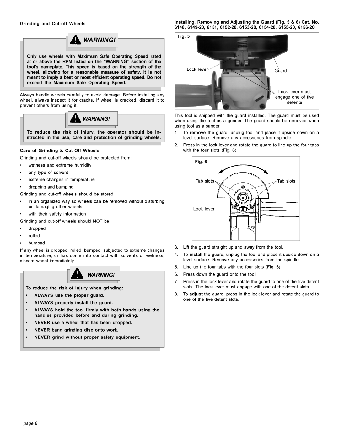
Installing, Removing and Adjusting the Guard (Fig. 5 & 6) Cat. No. 6148,
Fig. 5
Lock lever | Guard |
|
Lock lever must
engage one of five
detents
This tool is shipped with the guard installed. The guard must be used when using the tool as a grinder. The guard should be removed when using tool as a sander.
1.To remove the guard, unplug tool and place it upside down on a level surface. Remove any accessories from spindle.
2.Press in the lock lever and rotate the guard to line up the four tabs with the four slots (Fig. 6).
Fig. 6
Tab slots | Tab slots |
Lock lever
3.Lift the guard straight up and away from the tool.
4.To install the guard, unplug the tool and place it upside down on a level surface. Remove any accessories from the spindle.
5.Line up the four tabs with the four slots (Fig. 6).
6.Press down the guard onto the tool.
7.Press in the lock lever and rotate the guard to one of the five detent slots. The lock lever must engage with one of the detent slots.
8.To adjust the guard, press in the lock lever and rotate the guard to one of the five detent slots.
page 8
