3. DISPLAYS AND ALARMS
1.Load level and battery capacity is represented by 5 LEDs on the upper half of control panel (the 6th LED means FAULT).
(A). When the UPS is in the
Figure | Figure |
(B). During an AC line power failure, these 5 LEDs represent the remaining battery capacity. The LED’s will extinguish by the sequence from bottom to top as the battery voltage level decreases.
Figure 3.1-3 Battery Mode
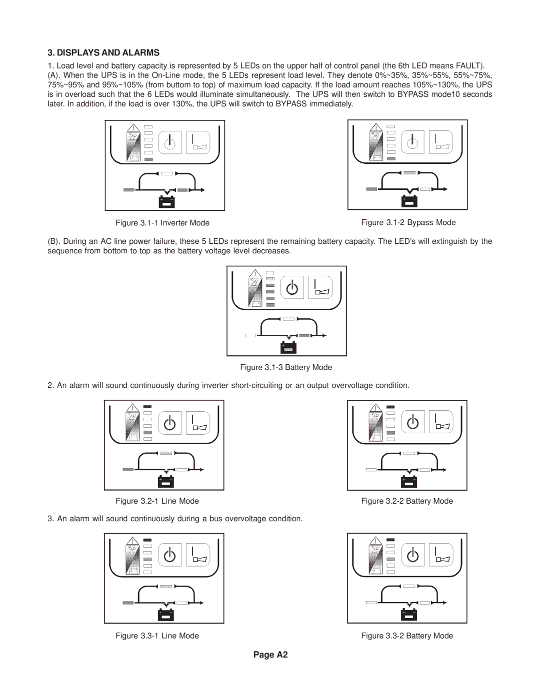
2. An alarm will sound continuously during inverter short-circuiting or an output overvoltage condition.
Figure | Figure |
3. An alarm will sound continuously during a bus overvoltage condition.
Figure | Figure |
Page A2