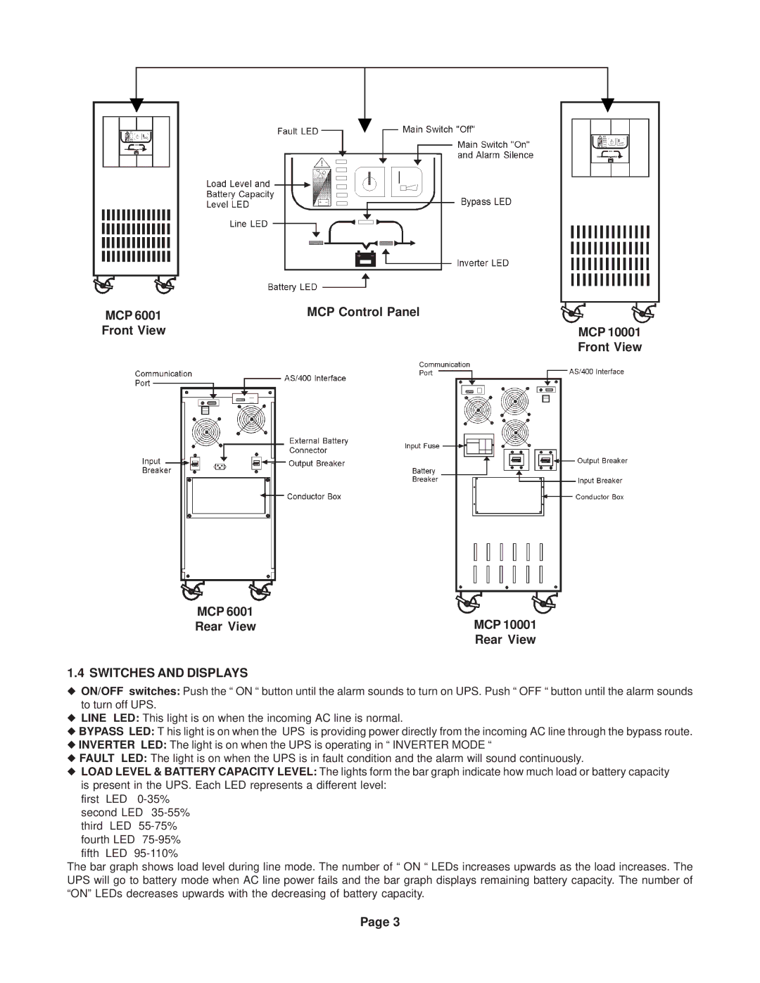
MCP 6001 | MCP Control Panel |
Front View | MCP 10001 |
| Front View |
MCP 6001
Rear ViewMCP 10001
Rear View
1.4 SWITCHES AND DISPLAYS
◆ON/OFF switches: Push the “ ON “ button until the alarm sounds to turn on UPS. Push “ OFF “ button until the alarm sounds to turn off UPS.
◆LINE LED: This light is on when the incoming AC line is normal.
◆BYPASS LED: T his light is on when the UPS is providing power directly from the incoming AC line through the bypass route.
◆INVERTER LED: The light is on when the UPS is operating in “ INVERTER MODE “
◆FAULT LED: The light is on when the UPS is in fault condition and the alarm will sound continuously.
◆LOAD LEVEL & BATTERY CAPACITY LEVEL: The lights form the bar graph indicate how much load or battery capacity is present in the UPS. Each LED represents a different level:
first LED
fifth LED
The bar graph shows load level during line mode. The number of “ ON “ LEDs increases upwards as the load increases. The UPS will go to battery mode when AC line power fails and the bar graph displays remaining battery capacity. The number of “ON” LEDs decreases upwards with the decreasing of battery capacity.
Page 3