4. Loading and Installation
The following is explanations of the handling precautions and installation environment which is common to modules when handling E71 from unpacking to installation.
For the details of loading and installation of the module, refer to User’s Manual of CPU module to be used.
4.1 Handling Precautions
The following is an explanation of handling precautions of the module.
(1)Because the case of the module is made of resin, be careful not to drop it or expose it to strong impact.
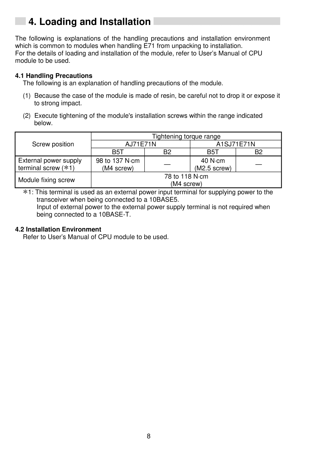
(2)Execute tightening of the module's installation screws within the range indicated below.
Screw position |
| Tightening torque range |
| ||
AJ71E71N | A1SJ71E71N | ||||
| B5T | B2 | B5T | B2 | |
External power supply | 98 to 137 N⋅cm | — | 40 N⋅cm | — | |
terminal screw ( 1) | (M4 screw) | (M2.5 screw) | |||
|
| ||||
Module fixing screw |
| 78 to 118 | N⋅cm |
| |
| (M4 screw) |
| |||
|
|
| |||
![]() 1: This terminal is used as an external power input terminal for supplying power to the transceiver when being connected to a 10BASE5.
1: This terminal is used as an external power input terminal for supplying power to the transceiver when being connected to a 10BASE5.
Input of external power to the external power supply terminal is not required when being connected to a
4.2 Installation Environment
Refer to User’s Manual of CPU module to be used.
8