Remark |
|
|
|
| |
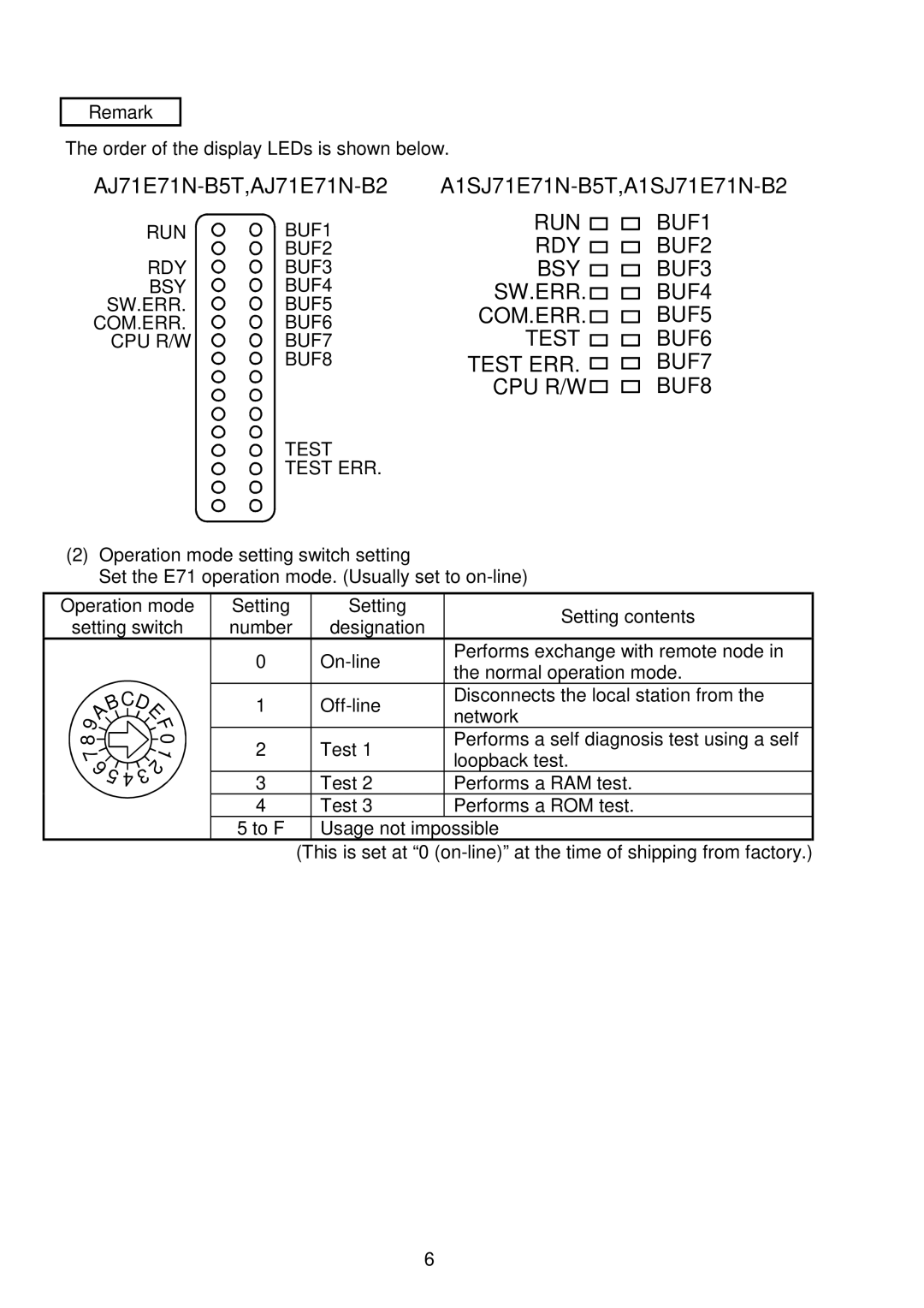
The order of the display LEDs is shown below. |
| ||||
RUN | BUF1 | RUN | BUF1 | ||
RDY | BUF2 | ||||
|
| BUF2 | |||
RDY | BUF3 | BSY | BUF3 | ||
BSY | BUF4 | SW.ERR. | BUF4 | ||
SW.ERR. | BUF5 | COM.ERR. | BUF5 | ||
COM.ERR. | BUF6 | ||||
CPU R/W | BUF7 | TEST | BUF6 | ||
|
| BUF8 | TEST ERR. | BUF7 | |
|
|
| CPU R/W | BUF8 | |
TEST
TEST ERR.
(2)Operation mode setting switch setting
Set the E71 operation mode. (Usually set to
Operation mode | Setting | Setting | Setting contents | |
setting switch | number | designation | ||
| ||||
| 0 | Performs exchange with remote node in | ||
| the normal operation mode. | |||
|
|
|
B 9A 8
7 65
CD | 1 | Disconnects the local station from the | ||
| E | network | ||
| F |
|
| |
| 0 | 2 | Test 1 | Performs a self diagnosis test using a self |
| 1 | loopback test. | ||
| 2 |
|
| |
|
|
|
| |
4 | 3 | 3 | Test 2 | Performs a RAM test. |
| ||||
|
| 4 | Test 3 | Performs a ROM test. |
5 to F Usage not impossible
(This is set at “0
6