Port Configuration
In order to determine the proper port configuration of the 232MSS2, it is necessary to have a basic understanding of the terms DCE and DTE.
If an IBM PC (DTE device) is going to be connected to the 232MSS2 master port, the master port should be configured as a DCE port. If a modem (DCE device) is going to be connected to the master port, it should be configured as a DTE port.
The master port can be configured as a DCE port (data received on pin 2) or a DTE port (data received on pin 3) by setting dipswitch “SW1”, position 8. To configure the master port as a DCE port, move dipswitch “SW1”, position 8, to the "OFF" position. When the master port is configured as a DCE port, ports A, B, C, & D will become DTE ports (Refer to Table 2). To configure the master port as a DTE port move dipswitch “SW1”, position 8, to the "ON" position. When the master port is configured as a DTE port, ports A, B, C, & D will become DCE ports (Refer to Table 3). Always power down the smart switch when changing switch settings.
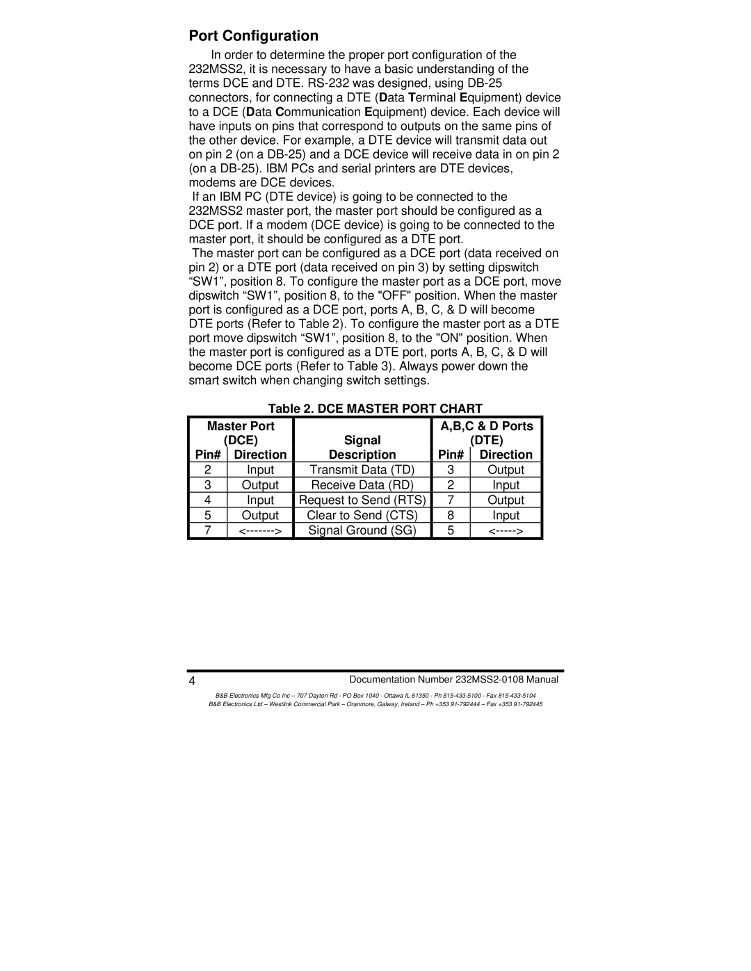
Table 2. DCE MASTER PORT CHART
Master Port |
| A,B,C & D Ports | |||
| (DCE) | Signal |
| (DTE) | |
Pin# |
| Direction | Description | Pin# | Direction |
2 |
| Input | Transmit Data (TD) | 3 | Output |
3 |
| Output | Receive Data (RD) | 2 | Input |
4 |
| Input | Request to Send (RTS) | 7 | Output |
5 |
| Output | Clear to Send (CTS) | 8 | Input |
7 |
| Signal Ground (SG) | 5 | ||
4Documentation Number
B&B Electronics Mfg Co Inc – 707 Dayton Rd - PO Box 1040 - Ottawa IL 61350 - Ph
B&B Electronics Ltd – Westlink Commercial Park – Oranmore, Galway, Ireland – Ph +353