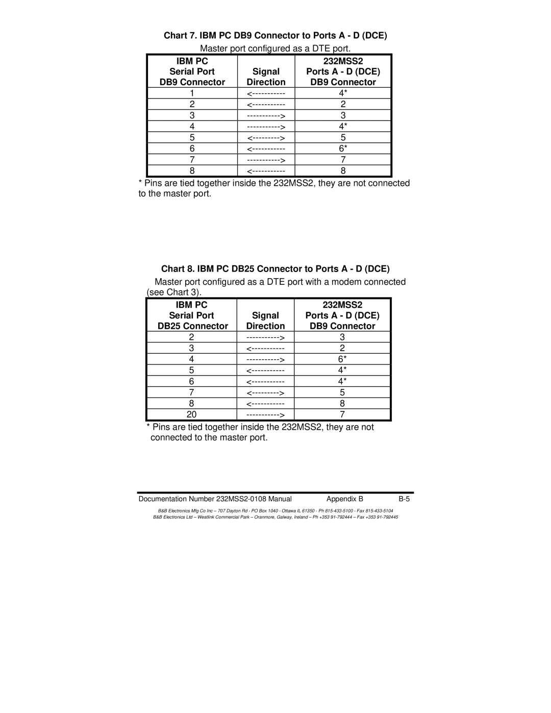
Chart 7. IBM PC DB9 Connector to Ports A - D (DCE)
Master port configured as a DTE port.
IBM PC |
|
|
|
Serial Port |
| Signal |
|
DB9 Connector | Direction |
| |
1 |
| ||
2 |
| ||
3 | > |
| |
4 | > |
| |
5 | > |
| |
6 |
| ||
7 | > |
| |
8 |
| ||
232MSS2
Ports A - D (DCE)
DB9 Connector
4*
2
3
4*
5
6*
7
8
*Pins are tied together inside the 232MSS2, they are not connected to the master port.
Chart 8. IBM PC DB25 Connector to Ports A - D (DCE)
Master port configured as a DTE port with a modem connected
(see Chart 3). |
|
|
|
|
IBM PC |
|
|
| 232MSS2 |
Serial Port |
| Signal |
| Ports A - D (DCE) |
DB25 Connector | Direction |
| DB9 Connector | |
2 | > |
| 3 | |
3 |
| 2 | ||
4 | > |
| 6* | |
5 |
| 4* | ||
6 |
| 4* | ||
7 | > |
| 5 | |
8 |
| 8 | ||
20 | > |
| 7 | |
*Pins are tied together inside the 232MSS2, they are not connected to the master port.
Documentation Number | Appendix B |
B&B Electronics Mfg Co Inc – 707 Dayton Rd - PO Box 1040 - Ottawa IL 61350 - Ph
B&B Electronics Ltd – Westlink Commercial Park – Oranmore, Galway, Ireland – Ph +353