Chapter 2: SETUP
The 232MSS2 is set up using an
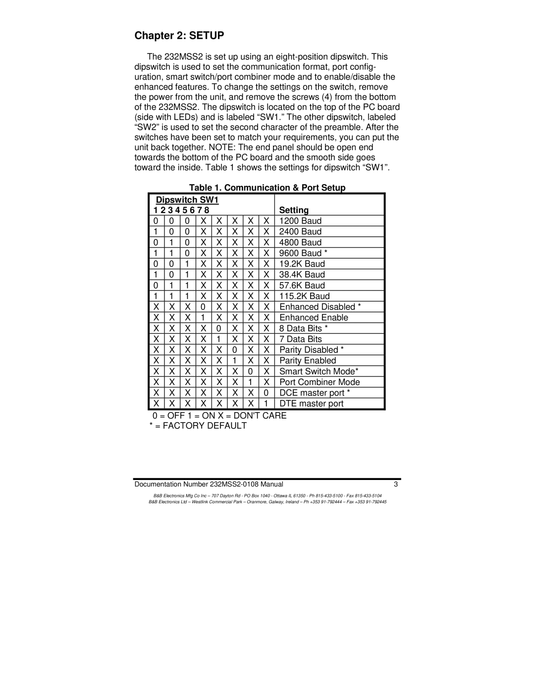
Table 1. Communication & Port Setup
Dipswitch SW1 |
|
|
|
| ||||
1 2 3 4 5 6 7 8 |
|
|
|
| Setting | |||
0 | 0 | 0 | X | X | X | X | X | 1200 Baud |
1 | 0 | 0 | X | X | X | X | X | 2400 Baud |
0 | 1 | 0 | X | X | X | X | X | 4800 Baud |
1 | 1 | 0 | X | X | X | X | X | 9600 Baud * |
0 | 0 | 1 | X | X | X | X | X | 19.2K Baud |
1 | 0 | 1 | X | X | X | X | X | 38.4K Baud |
0 | 1 | 1 | X | X | X | X | X | 57.6K Baud |
1 | 1 | 1 | X | X | X | X | X | 115.2K Baud |
X | X | X | 0 | X | X | X | X | Enhanced Disabled * |
X | X | X | 1 | X | X | X | X | Enhanced Enable |
X | X | X | X | 0 | X | X | X | 8 Data Bits * |
X | X | X | X | 1 | X | X | X | 7 Data Bits |
X | X | X | X | X | 0 | X | X | Parity Disabled * |
X | X | X | X | X | 1 | X | X | Parity Enabled |
X | X | X | X | X | X | 0 | X | Smart Switch Mode* |
X | X | X | X | X | X | 1 | X | Port Combiner Mode |
X | X | X | X | X | X | X | 0 | DCE master port * |
X | X | X | X | X | X | X | 1 | DTE master port |
0 = OFF 1 = ON X = DON'T CARE * = FACTORY DEFAULT
Documentation Number | 3 |
B&B Electronics Mfg Co Inc – 707 Dayton Rd - PO Box 1040 - Ottawa IL 61350 - Ph
B&B Electronics Ltd – Westlink Commercial Park – Oranmore, Galway, Ireland – Ph +353