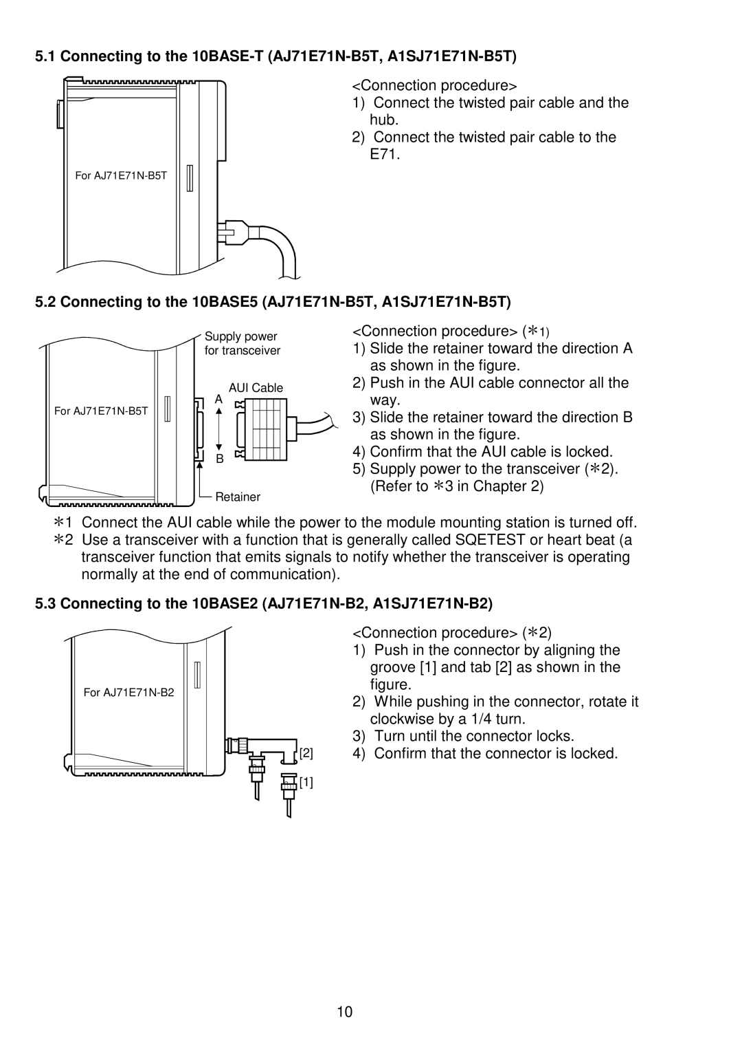
5.1 Connecting to the 10BASE-T (AJ71E71N-B5T, A1SJ71E71N-B5T)
<Connection procedure>
1) Connect the twisted pair cable and the hub.
2) Connect the twisted pair cable to the
E71.
For
5.2 Connecting to the 10BASE5 (AJ71E71N-B5T, A1SJ71E71N-B5T)
Supply power for transceiver
AUI Cable
A
For
B
Retainer
<Connection procedure> ( ![]() 1)
1)
1)Slide the retainer toward the direction A as shown in the figure.
2)Push in the AUI cable connector all the way.
3)Slide the retainer toward the direction B as shown in the figure.
4)Confirm that the AUI cable is locked.
5)Supply power to the transceiver ( ![]() 2). (Refer to
2). (Refer to ![]() 3 in Chapter 2)
3 in Chapter 2)
![]() 1 Connect the AUI cable while the power to the module mounting station is turned off.
1 Connect the AUI cable while the power to the module mounting station is turned off.
![]() 2 Use a transceiver with a function that is generally called SQETEST or heart beat (a transceiver function that emits signals to notify whether the transceiver is operating normally at the end of communication).
2 Use a transceiver with a function that is generally called SQETEST or heart beat (a transceiver function that emits signals to notify whether the transceiver is operating normally at the end of communication).
5.3 Connecting to the 10BASE2 (AJ71E71N-B2, A1SJ71E71N-B2)
For
<Connection procedure> ( ![]() 2)
2)
1)Push in the connector by aligning the groove [1] and tab [2] as shown in the figure.
2)While pushing in the connector, rotate it clockwise by a 1/4 turn.
3)Turn until the connector locks.
[2]4) Confirm that the connector is locked.
![]() [1]
[1]
10