Major operations and their functions (continued)
Rear view
1 |
|
| 2 |
|
|
| 3 |
|
|
|
|
|
|
|
|
|
|
| 4 | 5 | 6 |
| 7 | 8 |
|
|
|
|
|
|
| ||||||||||||||||||||||||||||||||||||||||||||||
|
|
|
|
|
|
|
|
|
|
|
|
|
|
|
|
|
|
|
|
|
|
|
|
|
|
|
|
|
|
|
|
|
|
|
|
|
|
|
|
|
|
|
|
|
|
|
|
|
|
|
|
|
|
|
|
|
|
|
|
|
|
|
|
|
|
|
|
|
|
|
|
|
|
|
|
|
|
|
|
|
|
|
|
|
|
|
|
|
|
|
|
|
|
|
|
|
|
|
|
|
|
|
|
|
|
|
|
|
|
|
|
|
|
|
|
|
|
|
|
|
|
|
|
|
|
|
|
|
|
|
|
|
|
|
|
|
|
|
|
|
|
|
|
|
|
|
|
|
|
|
|
|
|
|
|
|
|
|
|
|
|
|
|
|
|
|
|
|
|
|
|
|
|
|
|
|
|
|
|
|
|
|
|
|
|
|
|
|
|
|
|
|
|
|
|
|
|
|
|
|
|
|
|
|
|
|
|
|
|
|
|
|
|
|
|
|
|
|
|
|
|
|
|
|
|
|
|
|
|
|
|
|
|
|
|
|
|
|
|
|
|
|
|
|
|
|
|
|
|
|
|
|
|
|
|
|
|
|
|
|
|
|
|
|
|
|
|
|
|
|
|
|
|
|
|
|
|
|
|
|
|
|
|
|
|
|
|
|
|
|
|
|
|
|
|
|
|
|
|
|
|
|
|
|
|
|
|
|
|
|
|
|
|
|
|
|
|
|
|
|
|
|
|
|
|
|
|
|
|
|
|
|
|
|
|
|
|
|
|
|
|
|
|
|
|
|
|
|
|
|
|
|
|
|
|
|
|
|
|
|
|
|
|
|
|
|
|
|
|
|
|
|
|
|
|
|
|
|
|
|
|
|
|
|
|
|
|
|
|
|
|
|
|
|
|
|
|
|
|
|
|
|
|
|
|
|
|
|
|
|
|
|
|
|
|
|
|
|
|
|
|
|
|
|
|
|
|
|
|
|
|
|
|
|
|
|
|
|
|
|
|
|
|
|
|
|
|
|
|
|
|
|
|
|
|
|
|
|
|
|
|
|
|
|
|
|
|
|
|
|
|
|
|
|
|
|
|
|
|
|
|
|
|
|
|
|
|
|
|
|
|
|
|
|
|
|
|
|
|
|
|
|
|
|
|
|
|
|
|
|
|
|
|
|
|
|
|
|
|
|
|
|
|
|
|
|
|
|
|
|
|
|
|
|
|
|
|
|
|
|
|
|
|
|
|
|
|
|
|
|
|
|
|
|
|
|
|
|
|
|
|
|
|
|
|
|
|
|
|
|
|
|
|
|
|
|
|
|
|
|
|
|
|
|
|
|
|
|
|
|
|
|
|
|
|
|
|
|
|
|
|
|
|
|
|
|
|
|
|
|
|
|
|
|
|
|
|
|
|
|
|
|
|
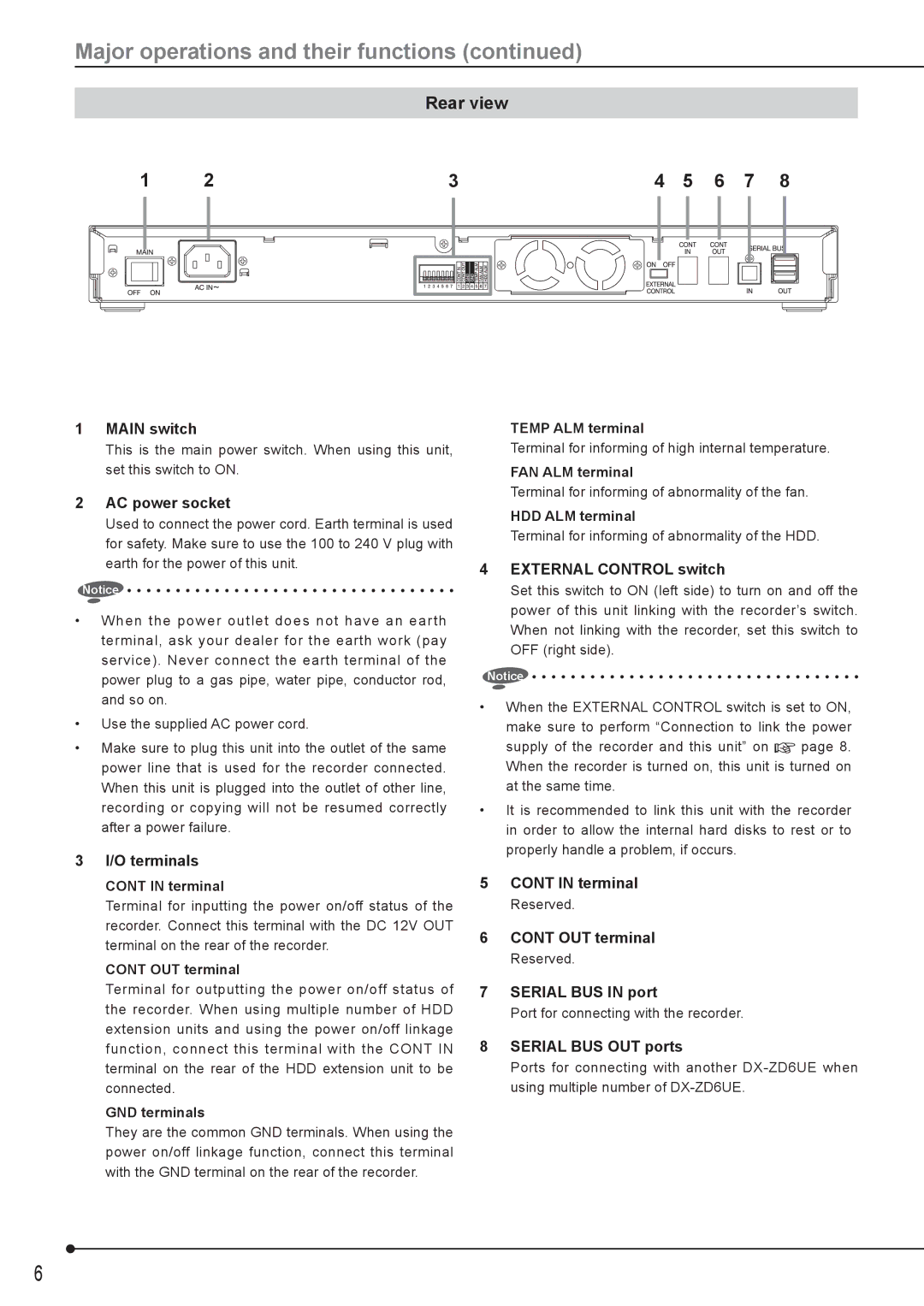
1MAIN switch
This is the main power switch. When using this unit, set this switch to ON.
2AC power socket
Used to connect the power cord. Earth terminal is used for safety. Make sure to use the 100 to 240 V plug with earth for the power of this unit.
Notice
•When the power outlet does not have an earth terminal, ask your dealer for the earth work (pay service). Never connect the earth terminal of the power plug to a gas pipe, water pipe, conductor rod, and so on.
•Use the supplied AC power cord.
•Make sure to plug this unit into the outlet of the same power line that is used for the recorder connected. When this unit is plugged into the outlet of other line, recording or copying will not be resumed correctly after a power failure.
3I/O terminals
CONT IN terminal
Terminal for inputting the power on/off status of the recorder. Connect this terminal with the DC 12V OUT terminal on the rear of the recorder.
CONT OUT terminal
Terminal for outputting the power on/off status of the recorder. When using multiple number of HDD extension units and using the power on/off linkage function, connect this terminal with the CONT IN terminal on the rear of the HDD extension unit to be connected.
GND terminals
They are the common GND terminals. When using the power on/off linkage function, connect this terminal with the GND terminal on the rear of the recorder.
TEMP ALM terminal
Terminal for informing of high internal temperature.
FAN ALM terminal
Terminal for informing of abnormality of the fan.
HDD ALM terminal
Terminal for informing of abnormality of the HDD.
4EXTERNAL CONTROL switch
Set this switch to ON (left side) to turn on and off the power of this unit linking with the recorder’s switch. When not linking with the recorder, set this switch to OFF (right side).
Notice
•When the EXTERNAL CONTROL switch is set to ON, make sure to perform “Connection to link the power
supply of the recorder and this unit” on ![]() page 8. When the recorder is turned on, this unit is turned on at the same time.
page 8. When the recorder is turned on, this unit is turned on at the same time.
•It is recommended to link this unit with the recorder in order to allow the internal hard disks to rest or to properly handle a problem, if occurs.
5CONT IN terminal
Reserved.
6CONT OUT terminal
Reserved.
7SERIAL BUS IN port
Port for connecting with the recorder.
8SERIAL BUS OUT ports
Ports for connecting with another
6