LDT651P specifications
The Mitsubishi Electronics LDT651P is a state-of-the-art 65-inch professional display that is designed to meet the diverse needs of various commercial applications. This model stands out with its superior picture quality, advanced technology, and robust build, making it an excellent choice for environments like retail spaces, corporate settings, and public venues.One of the main features of the LDT651P is its stunning 4K Ultra HD resolution, providing a crisp and vibrant display that maximizes visual clarity. With a resolution of 3840 x 2160 pixels, this display is capable of conveying intricate details across a wide range of content, from high-definition videos to detailed images, ensuring that every piece of information is presented in the best possible light.
The LDT651P utilizes advanced LED backlighting technology, which enhances brightness and contrast while maintaining energy efficiency. This results in a display that is not only bright and eye-catching but also economical, an essential characteristic in commercial settings where displays are often left on for extended periods. The incorporation of high dynamic range (HDR) support further elevates the viewing experience, allowing for deeper blacks and brighter whites, thus providing a more lifelike image.
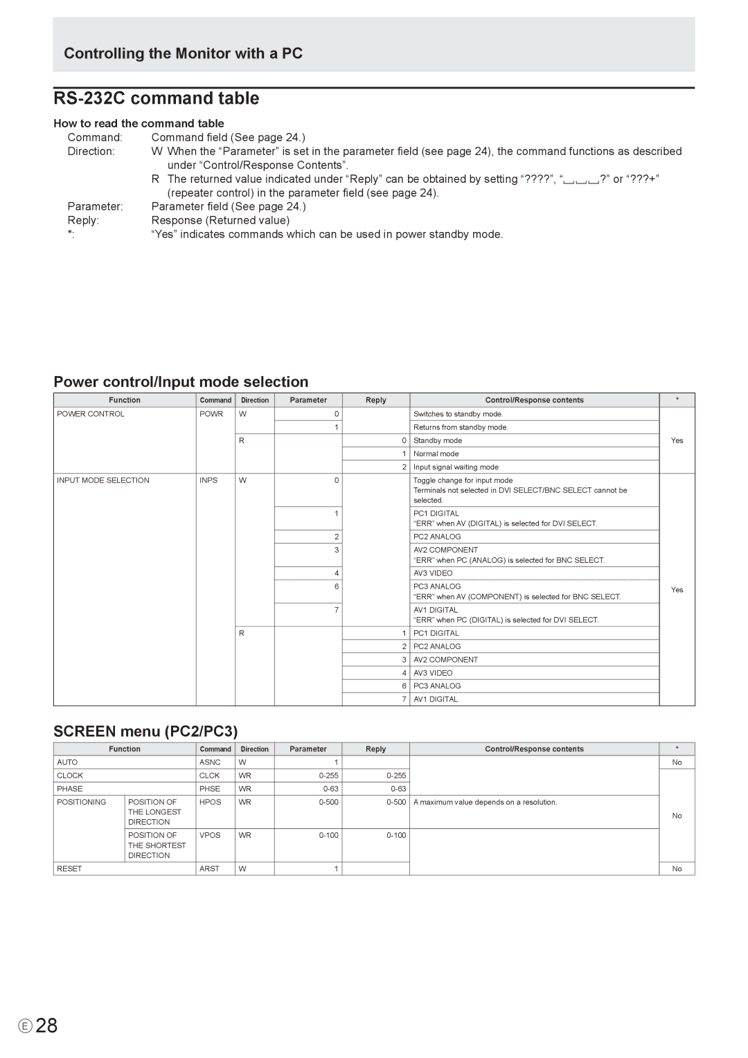
Equipped with multiple input options, including HDMI, DisplayPort, and USB ports, the LDT651P offers versatility for content connectivity. This flexibility enables seamless integration with a variety of devices, including computers, media players, and broadcasting equipment, making it easy for businesses to adapt the display to their specific needs.
The LDT651P is also designed with durability in mind. Its robust construction ensures that the display can withstand the rigors of daily use in busy environments, contributing to a longer lifespan. In addition, the display features a wide viewing angle, ensuring that content is visible from various positions, making it ideal for larger spaces where audiences gather.
Moreover, Mitsubishi has embedded remote management capabilities within the LDT651P, making it easier for operators to control multiple displays from a centralized location. This feature is particularly advantageous for businesses managing digital signage networks, as it enhances operational efficiency and reduces the need for manual adjustments.
In conclusion, the Mitsubishi Electronics LDT651P is a powerful display solution that combines unmatched picture quality, robust design, and versatile connectivity options. Its advanced technology makes it an ideal choice for commercial applications, ensuring engaging content delivery in any setting.

