2 PART NAME
2.1Control Names
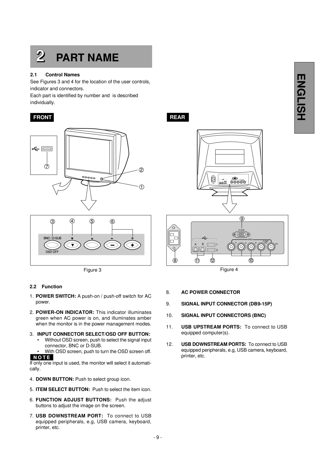
See Figures 3 and 4 for the location of the user controls,
indicator and connectors.
Each part is identified by number and is described
individually.
| FRONT |
|
|
|
|
| REAR | ||||
|
|
|
|
|
|
|
|
|
|
|
|
|
|
|
|
|
|
|
|
|
|
|
|
|
|
|
|
|
|
|
|
|
|
|
|
|
|
|
|
|
|
|
|
|
|
|
|
|
|
|
|
|
|
|
|
|
|
|
|
|
|
|
|
|
|
|
|
|
|
|
|
|
|
|
|
|
|
|
|
|
|
|
|
|
|
|
|
|
|
|
|
|
|
|
|
|
|
|
|
|
|
|
|
|
|
|
|
|
|
|
|
|
| |
|
|
|
| BNC | COMP. |
|
A | B | R | G | B | HD | VD |
1 |
|
|
| |||
|
| 2 |
|
|
|
|
ENGLISH
|
|
|
|
|
| |
|
|
|
| BNC | COMP. |
|
|
|
|
|
|
| |
A | B | R | G | B | HD | VD |
1 |
|
|
| |||
|
| 2 |
|
|
|
|
Figure 3 | Figure 4 |
2.2Function
1.POWER SWITCH: A push-on / push-off switch for AC power.
2.
3.INPUT CONNECTOR SELECT/OSD OFF BUTTON:
•Without OSD screen, push to select the signal input connector, BNC or
•With OSD screen, push to turn the OSD screen off.
If only one input is used, the monitor will select it automati- cally.
4.DOWN BUTTON: Push to select group icon.
5.ITEM SELECT BUTTON: Push to select the item icon.
6.FUNCTION ADJUST BUTTONS: Push the adjust buttons to adjust the image on the screen.
7.USB DOWNSTREAM PORT: To connect to USB equipped peripherals, e.g, USB camera, keyboard, printer, etc.
- 9 -
8.AC POWER CONNECTOR
9.SIGNAL INPUT CONNECTOR
10.SIGNAL INPUT CONNECTORS (BNC)
11.USB UPSTREAM PORTS: To connect to USB equipped computer(s).
12.USB DOWNSTREAM PORTS: To connect to USB equipped peripherals, e.g, USB camera, keyboard, printer, etc.