3INSTALLATION AND CONNECTION
On the back of the monitor four kinds of
3.1AC Power Connection
One end of the AC power cord is connected to the AC power connector on the back of the monitor. The other end is plugged into a properly grounded
3.2Signal Cable Connection
The
3.2.1Connecting to Any IBM VGA Compatible Sys- tem
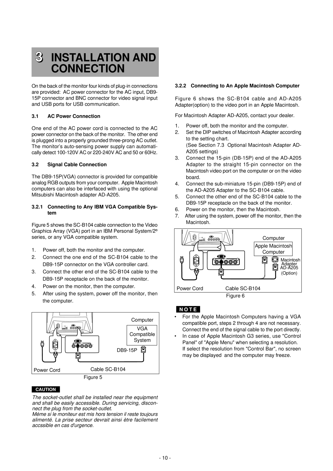
Figure 5 shows the SC-B104 cable connection to the Video Graphics Array (VGA) port in an IBM Personal System/2® series, or any VGA compatible system.
1.Power off, both the monitor and the computer.
2.Connect the one end of the SC-B104 cable to the DB9-15P connector on the VGA controller card.
3.Connect the other end of the SC-B104 cable to the DB9-15P receptacle on the back of the monitor.
4.Power on the monitor, then the computer.
5.After using the system, power off the monitor, then the computer.
3.2.2 Connecting to An Apple Macintosh Computer
Figure 6 shows the SC-B104 cable and AD-A205 Adapter(option) to the video port in an Apple Macintosh.
For Macintosh Adapter AD-A205, contact your dealer.
1.Power off, both the monitor and the computer.
2.Set the DIP switches of Macintosh Adapter according to the setting chart.
(See Section 7.3 Optional Macintosh Adapter AD- A205 settings)
3.Connect the 15-pin (DB-15P) end of the AD-A205 Adapter to the straight 15-pin connector on the Macintosh video port on the computer or on the video board.
4.Connect the sub-miniature 15-pin (DB9-15P) end of the AD-A205 Adapter to the SC-B104 cable.
5.Connect the other end of the SC-B104 cable to the DB9-15P receptacle on the back of the monitor.
6.Power on the monitor, then the Macintosh.
7.After using the system, power off the monitor, then the Macintosh.
A B | 2 |
| Computer |
1 |
|
| |
|
|
| Apple Macintosh |
|
| Computer | |
| R G | B HD VD | Macintosh |
|
| BNC |
|
|
| COMP. |
|
|
|
| Adapter |
|
|
| |
|
|
| (Option) |
Power Cord |
| Cable | |
|
| Figure 6 |
|
|
|
|
|
| Computer | • |
|
|
|
|
|
| |
A B | 1 |
|
|
| VGA |
|
| 2 |
|
|
|
| |
|
|
|
|
|
| |
|
|
|
|
| Compatible | • |
|
|
|
| System | ||
|
|
|
|
| ||
|
|
| BNC | COMP. |
| |
| R | G | B |
|
| |
| HD | VD |
| |||
|
|
|
|
|
|
|
Power Cord |
|
|
|
| Cable |
|
Figure 5
CAUTION
The
Méme si le moniteur est mis hors tension il reste toujours alimenté. La prise secteur devrait ainsi ètre facilement accssible en cas d'urgence.
For the Apple Macintosh Computers having a VGA compatible port, steps 2 through 4 are not necessary. Connect the end of the signal cable to the port directly. In case of Apple Macintosh G3 series, use "Control Panel" of "Apple Menu" when selecting a resolution.
If select the resolution from "Control Bar", no screen may be displayed and the computer may freeze.
- 10 -