3.2.3Connecting to a Unix Workstation & Third Party Graphics Card
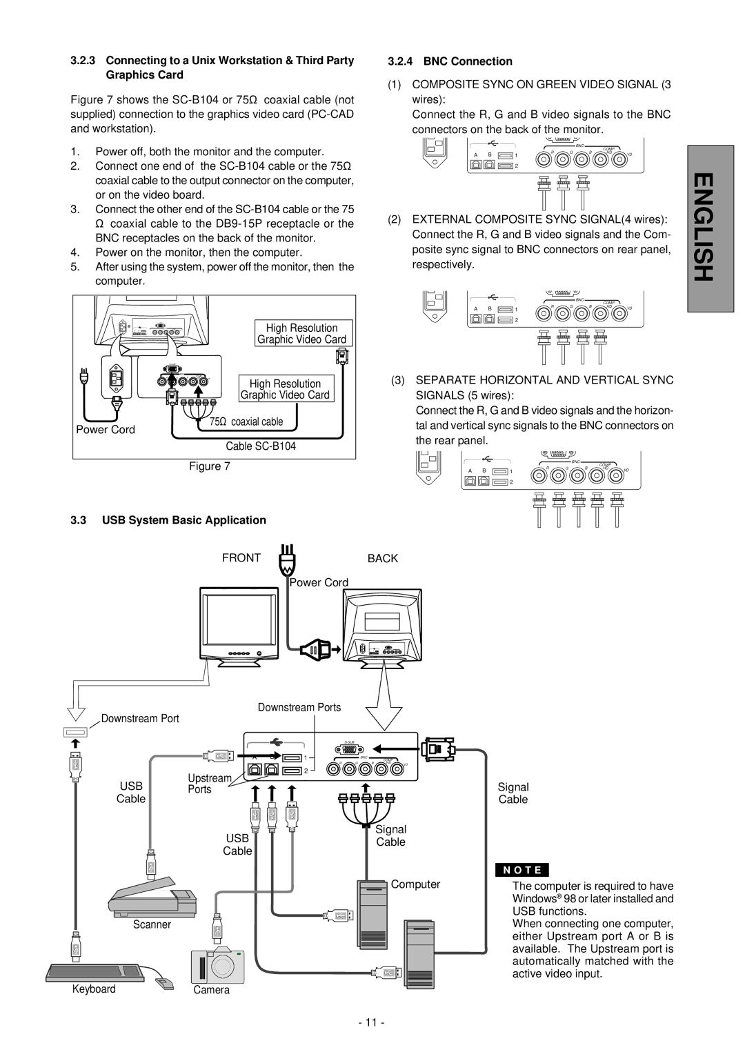
Figure 7 shows the SC-B104 or 75Ω coaxial cable (not supplied) connection to the graphics video card (PC-CAD and workstation).
1.Power off, both the monitor and the computer.
2.Connect one end of the SC-B104 cable or the 75Ω coaxial cable to the output connector on the computer, or on the video board.
3.Connect the other end of the SC-B104 cable or the 75 Ω coaxial cable to the DB9-15P receptacle or the BNC receptacles on the back of the monitor.
4.Power on the monitor, then the computer.
5.After using the system, power off the monitor, then the computer.
3.2.4BNC Connection
(1)COMPOSITE SYNC ON GREEN VIDEO SIGNAL (3 wires):
Connect the R, G and B video signals to the BNC connectors on the back of the monitor.
|
|
|
| BNC | COMP. |
|
|
|
|
|
|
| |
A | B | R | G | B | HD | VD |
1 |
|
|
|
2
(2)EXTERNAL COMPOSITE SYNC SIGNAL(4 wires): Connect the R, G and B video signals and the Com- posite sync signal to BNC connectors on rear panel, respectively.
ENGLISH
|
|
|
|
|
|
|
|
|
|
| BNC | COMP. |
|
|
|
|
|
|
|
|
|
|
|
|
|
| |
|
|
|
|
|
|
|
| A B | R | G | B | HD | VD |
|
|
|
|
|
|
|
| 1 |
|
|
| ||
|
|
|
|
|
|
| High Resolution |
| 2 |
|
|
|
|
A | B | 12 |
|
|
|
|
|
|
|
|
|
| |
|
|
|
|
|
|
| Graphic Video Card |
|
|
|
|
|
|
|
|
|
|
|
|
|
|
|
|
|
|
| |
|
|
|
| BNC |
|
|
| (3) SEPARATE HORIZONTAL AND VERTICAL SYNC | |||||
|
| R | G | B | COMP. |
| High Resolution | ||||||
|
| HD | VD | ||||||||||
|
|
|
|
|
|
| Graphic Video Card | SIGNALS (5 wires): |
|
|
|
|
|
|
|
|
|
|
| 75Ω coaxial cable | Connect the R, G and B video signals and the horizon- | ||||||
Power Cord |
|
|
|
|
| tal and vertical sync signals to the BNC connectors on | |||||||
|
|
|
|
|
|
| |||||||
|
|
|
|
|
|
| the rear panel. |
|
|
|
|
| |
|
|
|
|
|
|
| Cable |
|
|
|
|
| |
|
|
|
|
|
|
|
|
|
|
|
|
| |
Figure 7 |
| R | G | BNC | HD | VD |
| B | |||||
|
|
|
|
| COMP. |
|
| A B | 1 |
|
|
|
|
2
3.3 USB System Basic Application
FRONTBACK
Power Cord
Downstream Ports
Downstream Port
|
|
|
| |
1 |
| BNC | COMP. |
|
|
|
| ||
R | G | B | HD | VD |
|
|
|
|
2
Upstream
USB Ports
Cable
USB | Signal | |
Cable | ||
Cable | ||
| ||
| Computer |
Scanner
KeyboardCamera
Signal
Cable
N O T E
�The computer is required to have Windows® 98 or later installed and USB functions.
�When connecting one computer, either Upstream port A or B is available. The Upstream port is automatically matched with the active video input.
- 11 -