4. Installing the refrigerant piping

1

1-3/8 E

D

(inch)


11-1/32


C


22-7/8

2-1/8

-7/32

B

B

17-11/16

3-3/8

1


D


C 27-9/16 A

6-1/32 F


Fig. 4-2


4.3. Positioning refrigerant and drain piping

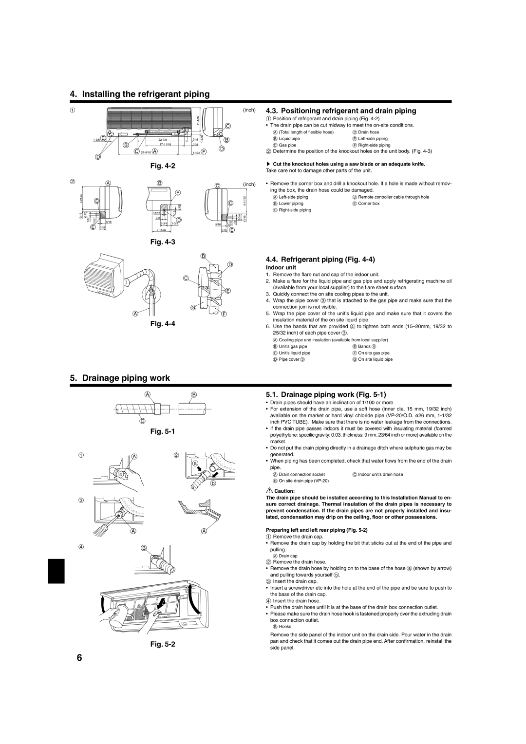
1Position of refrigerant and drain piping (Fig. 4-2)

The drain pipe can be cut midway to meet the on-site conditions.

A (Total length of flexible hose)

D Drain hose

B Liquid pipe

E Left-side piping

C Gas pipe

F Right-side piping

2Determine the position of the knockout holes on the unit body. (Fig. 4-3)

sCut the knockout holes using a saw blade or an adequate knife. Take care not to damage other parts of the unit.

2


A

B


C


(inch)


9-21/32


E


D


D


21/32


-


3/8


9


2-


13/16

2-3/4

7/8

13/32


5/16

5/16

13/32

7/8

-23/4

13/16


2-3/4 1-3/8


13/32


7/8

D


5/16


E 2-3/8


7-15/32


2-3/8

E


Fig. 4-3

B

D

C

E

G

AF

Fig. 4-4

Remove the corner box and drill a knockout hole. If a hole is made without remov- ing the box, the drain hose could be damaged.

A Left-side piping

D Remote controller cable through hole

B Lower piping

E Corner box

CRight-side piping

4.4. Refrigerant piping (Fig. 4-4)

Indoor unit

1.Remove the flare nut and cap of the indoor unit.

2.Make a flare for the liquid pipe and gas pipe and apply refrigerating machine oil (available from your local supplier) to the flare sheet surface.

3.Quickly connect the on site cooling pipes to the unit.

4.Wrap the pipe cover 3 that is attached to the gas pipe and make sure that the connection join is not visible.

5.Wrap the pipe cover of the unit’s liquid pipe and make sure that it covers the insulation material of the on site liquid pipe.

6.Use the bands that are provided 4 to tighten both ends (15–20mm, 19/32 to 25/32 inch) of each pipe cover 3.

ACooling pipe and insulation (available from local supplier)

B Unit’s gas pipe

E Bands 4

C Unit’s liquid pipe

F On site gas pipe

D Pipe cover 3

G On site liquid pipe

5. Drainage piping work

AB


C


Fig. 5-1

1

A

2

a

b

3

AA

4B

Fig. 5-2

5.1. Drainage piping work (Fig. 5-1)

Drain pipes should have an inclination of 1/100 or more.

For extension of the drain pipe, use a soft hose (inner dia. 15 mm, 19/32 inch) available on the market or hard vinyl chloride pipe (VP-20/O.D. ø26 mm, 1-1/32 inch PVC TUBE). Make sure that there is no water leakage from the connections.

If the drain pipe passes indoors it must be covered with insulating material (foamed polyethylene: specific gravity: 0.03, thickness: 9 mm, 23/64 inch or more) available on the market.

Do not put the drain piping directly in a drainage ditch where sulphuric gas may be generated.

When piping has been completed, check that water flows from the end of the drain pipe.

A Drain connection socket

C Indoor unit’s drain hose

BOn site drain pipe (VP-20)

Caution:

The drain pipe should be installed according to this Installation Manual to en- sure correct drainage. Thermal insulation of the drain pipes is necessary to prevent condensation. If the drain pipes are not properly installed and insu- lated, condensation may drip on the ceiling, floor or other possessions.

Preparing left and left rear piping (Fig. 5-2)

1Remove the drain cap.

Remove the drain cap by holding the bit that sticks out at the end of the pipe and

pulling.

ADrain cap

2Remove the drain hose.

Remove the drain hose by holding on to the base of the hose a (shown by arrow) and pulling towards yourself b.

3Insert the drain cap.

Insert a screwdriver etc into the hole at the end of the pipe and be sure to push to the base of the drain cap.

4Insert the drain hose.

Push the drain hose until it is at the base of the drain box connection outlet.

Please make sure the drain hose hook is fastened properly over the extruding drain box connection outlet.

B Hooks

Remove the side panel of the indoor unit on the drain side. Pour water in the drain pan and check that it comes out the drain pipe end. After confirmation, reinstall the side panel.

6

Page 6
Image 6
Mitsubishi Electronics PKA-A-GA Drainage piping work, Positioning refrigerant and drain piping, Refrigerant piping Fig

PKA-A-GA specifications

Mitsubishi Electronics has long been a key player in the realm of air conditioning and climate control technologies, offering a range of innovative solutions that cater to both residential and commercial needs. Among their impressive lineup, the Mitsubishi PKA-A-GA stands out as a noteworthy model known for its advanced features, efficiency, and reliability.

The Mitsubishi PKA-A-GA is a wall-mounted air conditioning unit specifically designed for easy installation and optimal performance. One of its main features is the sleek and modern design, which allows it to blend seamlessly with various interior settings. Its compact form factor saves space while maximizing cooling efficiency.

This model utilizes cutting-edge inverter technology, which significantly enhances energy efficiency. By adjusting the compressor speed according to the cooling demand, the PKA-A-GA maintains a consistent temperature while reducing energy consumption. This not only lowers utility bills but also contributes to a more sustainable operation, making the unit eco-friendly.

A remarkable characteristic of the PKA-A-GA is its advanced air filtration system. Equipped with a high-performance filter, the unit effectively removes allergens, dust, and other particulates from the indoor air, ensuring a cleaner and healthier environment. Additionally, the unit features a self-cleaning function, which helps maintain the filter's efficiency by reducing the buildup of dust and other particles.

Another compelling aspect of the Mitsubishi PKA-A-GA is its whisper-quiet operation. The unit is designed to minimize noise, making it ideal for bedrooms, offices, and other spaces where tranquility is essential. This is particularly beneficial for users who require a calm atmosphere for work or relaxation.

Furthermore, the PKA-A-GA is compatible with smart controls, allowing users to operate and monitor their air conditioning system remotely via smartphones or tablets. This feature adds convenience and lets users optimize their energy consumption even when they're away from home.

Lastly, the durability of the Mitsubishi PKA-A-GA is noteworthy. Built with high-quality materials and robust components, this air conditioning unit is designed to withstand the rigors of daily use while providing reliable performance over the years.

Overall, the Mitsubishi PKA-A-GA is an exceptional air conditioning solution, blending efficiency, smart technology, and user-friendly features into a compact design. Whether for residential or commercial applications, it promises to deliver comfort and satisfaction in an ever-evolving climate.