Projection Television Owner’s Guide
Risk of Electric Shock
Contents
Important Safeguards
Important SAFEGUARDS, cont’d
Mitsubishi Digital Electronics America, Inc
Our Thanks
Television Overview
Chapter
Special Features
TV Accessories
Front Control Panel
POWER/TIMER Indicator
CableCARD Slot
Back Panel
IEEE-1394 Input/Output
Digital Audio Output
Component Inputs
IR Output-NetCommand
Hdmi or DVI Devices
DVI Analog Audio
Shopping channel logos & pricing displays
Letterbox top/bottom black bars
Side bar images
News and stock-market report bars
Connecting
Chart
Connecting External Devices & NetCommand Setup
Cable Box compatible with PIP/POP
Connecting a Wall Outlet Cable or Cable Box
For antennas with coaxial lead
Single Antenna
Separate UHF and VHF Antennas
For antennas with twin flat lead
Red
VCR to Antenna or Wall Outlet Cable
VCR to a Cable Box
Connecting VCR Video and Audio to a Cable Box
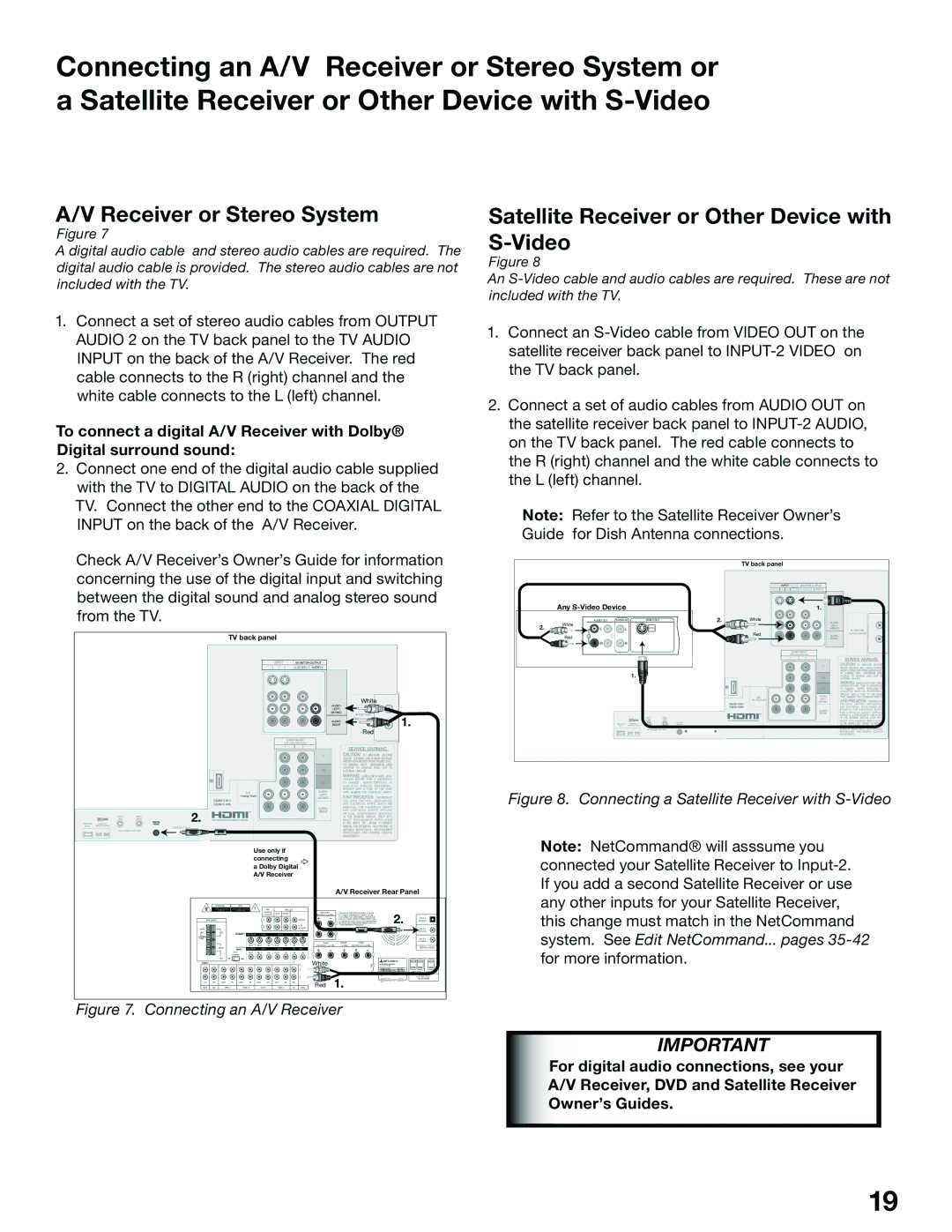
Satellite Receiver or Other Device with S-Video
Receiver or Stereo System
DVD Player with Component Video
Connecting a DVD Player with Component Video or DVI Device
DVI Device
External DTV Receiver with Component Video
Hdmi Device
IR Emitter NetCommand
Connecting the IR Emitter NetCommand
Pin Style vs -Pin Style
Connecting Ieee 1394 Devices
Hub Connection Style
Ieee 1394 Device Connection Styles
Connection Styles
Direct Device-To-Device Style
CableCARD Definition and Initial Screen Display
Using a CableCARD
CableCARD Technology
Connecting Helpful Hints
NetCommand Setup and Editing
Device
NetCommand Pre-Memorized Devices
Following
Remote Control Functions Overview
Care
Remote Control FunctionsOperation, Care, Sleep Timer
Sleep Timer
Operation
NetCommand On-Screen Buttons
3D Graphical Menu System
Remote Control Buttons
Welcome Screen
NetCommand Initial Setup
NetCommand Information Screen
Device Setup Screen
Finish Screen
Review Screen
Receiver Screen
Edit NetCommand, Adding an A/V Receiver
Receiver Inputs
Receiver Learn Screen
Receiver Input Learn Screen
Monitor Out to AVR Screen
Name Screen
Edit NetCommand
Edit NetCommand, Adding Devices
Device Screen
Add Screen
Device Advanced Learn Screen
Device Learn Screen
IR Code for Device Screen
Connection for Device Screen
VCR for Recordings Screen
RF Connection for Cable Screen
Delete Screen
Change Screen
Device Selection Menu
CableCARD Menu
Using the Device Menu Button to Display Menus
Device Menu
IR Controlled Devices/IEEE 1394 Menus
Ieee 1394 Devices and NetCommand Controlled Recordings
Name for 1394 Device Screen
Adding Ieee 1394 Devices Automatically
Adding Ieee 1394 Devices Automatically
New 1394 Device Screen
Connection Screen
Ieee 1394 Device Type Screen
Ieee 1394 Devices Compatibility
Digital Video Signals
Digital Audio Signals
Digital Control Signal
Using the Guide Button to Display ChannelView and Menus
Recording Now
NetCommand Controlled Recordings
Record To Setup
Time-Delayed Recording
Track List Screen
Cancel Current Recordings
Record List Screen
Disc Search
Direct VCR Recording from an Antenna or Cable Source
Direct VCR Recording
Restrictions for Traditional VCRs
Canceling a Current Peer-to-Peer Connection
NetCommand Controlled Peer-to-Peer Connections
What is a Peer-to-Peer Connection?
Setting up a Peer-to-Peer Connection
Important Notes
TV Menu Screen Operations
Main Menu Choices
Setup Menu
Advanced Convergence
Reset Factory Defaults Menu
NetCommand Menu
Antenna Menu
SQV SuperQuickView
Manual
Setting the Clock
Timer On/Off
Time Menu
Digital Captions
Captions Menu
Captions Menu
Analog Captions
Opacity Font
Fonts
Size
Color
Chip Start Time and V-Chip Stop Time
Chip Lock Menu
Chip
Entry
Content Categories
Chip Signal Information
TV Ratings
Front Button Lock
Lock By Time
AudioVideo
AudioVideo Menu
Digital Only Audio Settings
Setting Descriptions
Analog and Digital Audio Setting
Analog Only Audio Settings
Contrast
Video Settings
Chapter
DVD Definitions
Format Signals
Display Formats
Format Definitions
Original Signal
Changing PIP/POP Device
Operation of PIP and POP
Device Menu with Net Command
Ieee 1394 Devices Digital
Bypassing the V-Chip Lock
Appendix a Bypassing the V-Chip Lock
Bypassing Front Button Lock
This page intentionally blank
Appendix B High Definition Input Connection Compatibility
Input Levels and Timing with Component Video Signals
Component-1 and Component-2 Inputs
Programming the Remote to Control NetCommand A/V Products
Appendix CRemote Control Programming Codes
DVD Players
Appendix C Remote Control Programming Codes
Mitsubishi CD Players Not all functions for all models
Cable Boxes and Satellite Receivers
Receivers
Mitsubishi A/V Receivers
Appendix D On Screen Information Displays
Checkbox Name
Appendix E NetCommand Specialized Device Keys
Appendix F Cleaning and Service
For additional assistance, call 800
Appendix G Diamond Shield Removal for Models
For the WS-48515
For the WS-55515, WS-65515 and WS-65515A
For the WS-55615, WS-55615A, WS-65615 and WS-65615A
Appendix G, Diamond Shield Installation for Model WS-73615
WS-65515, WS-65515A, WS-65615, WS-65615A, WS-73615
Appendix H Cabinet Separation for Models
Problem Possible Solution
Troubleshooting
Troubleshooting
Troubleshooting
Using The System Reset Button
Additional Information
Demo Mode
Index
Menu 56
Mitsubishi Projection Television Limited Warranty
Mitsubishi Projection TV Limited Warranty
Mitsubishi TV Software
Page
Mitsubishi Digital Electronics America, Inc D405A10