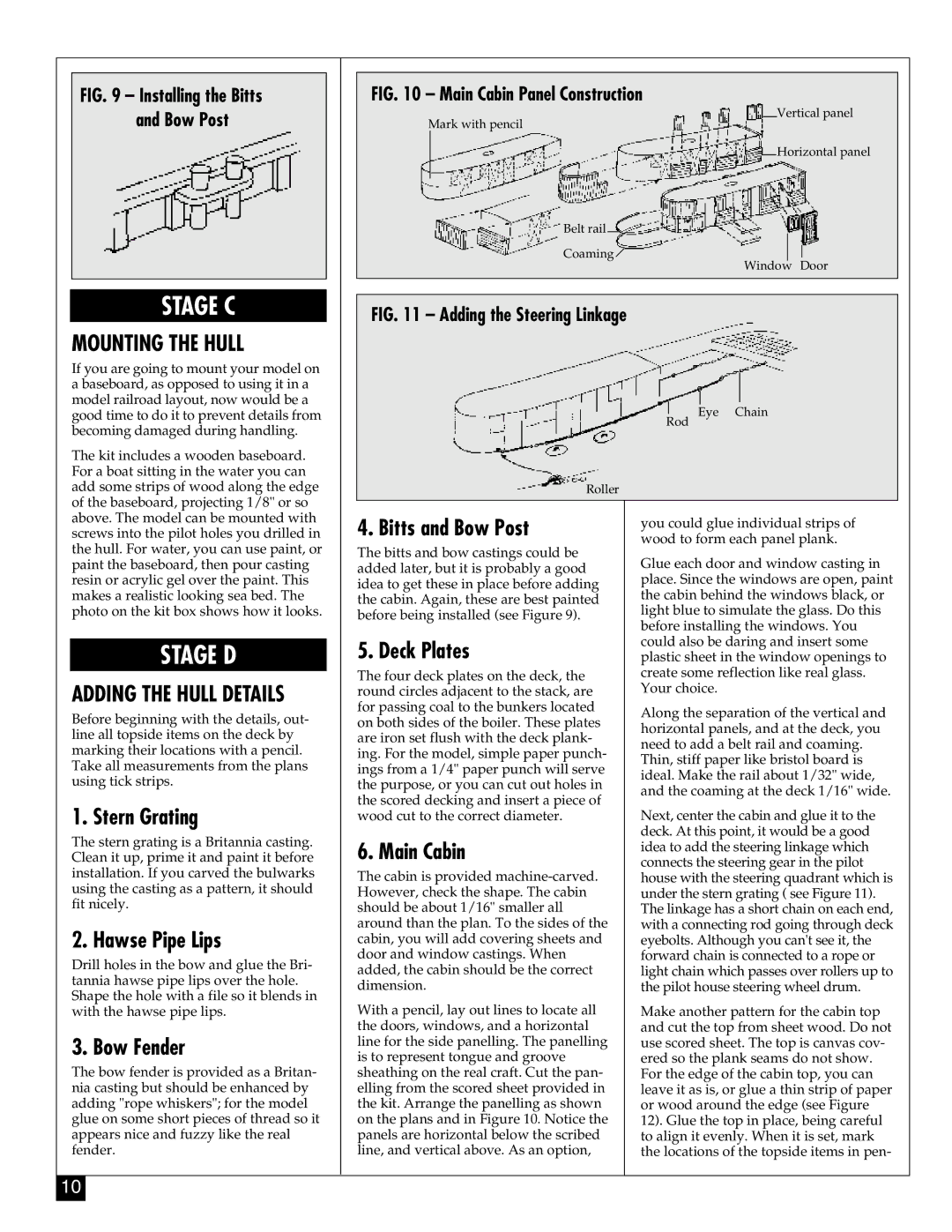
FIG. 9 – Installing the Bitts and Bow Post
STAGE C
MOUNTING THE HULL
If you are going to mount your model on a baseboard, as opposed to using it in a model railroad layout, now would be a good time to do it to prevent details from becoming damaged during handling.
The kit includes a wooden baseboard. For a boat sitting in the water you can add some strips of wood along the edge of the baseboard, projecting 1/8" or so above. The model can be mounted with
FIG. 10 – Main Cabin Panel Construction
Vertical panel
Mark with pencil
Horizontal panel
Belt rail
Coaming ![]()
Window Door
FIG. 11 – Adding the Steering Linkage
Eye Chain
Rod
Roller
screws into the pilot holes you drilled in the hull. For water, you can use paint, or paint the baseboard, then pour casting resin or acrylic gel over the paint. This makes a realistic looking sea bed. The photo on the kit box shows how it looks.
STAGE D
ADDING THE HULL DETAILS
Before beginning with the details, out- line all topside items on the deck by marking their locations with a pencil. Take all measurements from the plans using tick strips.
1. Stern Grating
The stern grating is a Britannia casting. Clean it up, prime it and paint it before installation. If you carved the bulwarks using the casting as a pattern, it should fit nicely.
2. Hawse Pipe Lips
Drill holes in the bow and glue the Bri- tannia hawse pipe lips over the hole. Shape the hole with a file so it blends in with the hawse pipe lips.
3. Bow Fender
The bow fender is provided as a Britan- nia casting but should be enhanced by adding "rope whiskers"; for the model glue on some short pieces of thread so it appears nice and fuzzy like the real fender.
4. Bitts and Bow Post
The bitts and bow castings could be added later, but it is probably a good idea to get these in place before adding the cabin. Again, these are best painted before being installed (see Figure 9).
5. Deck Plates
The four deck plates on the deck, the round circles adjacent to the stack, are for passing coal to the bunkers located on both sides of the boiler. These plates are iron set flush with the deck plank- ing. For the model, simple paper punch- ings from a 1/4" paper punch will serve the purpose, or you can cut out holes in the scored decking and insert a piece of wood cut to the correct diameter.
6. Main Cabin
The cabin is provided
With a pencil, lay out lines to locate all the doors, windows, and a horizontal line for the side panelling. The panelling is to represent tongue and groove sheathing on the real craft. Cut the pan- elling from the scored sheet provided in the kit. Arrange the panelling as shown on the plans and in Figure 10. Notice the panels are horizontal below the scribed line, and vertical above. As an option,
you could glue individual strips of wood to form each panel plank.
Glue each door and window casting in place. Since the windows are open, paint the cabin behind the windows black, or light blue to simulate the glass. Do this before installing the windows. You could also be daring and insert some plastic sheet in the window openings to create some reflection like real glass. Your choice.
Along the separation of the vertical and horizontal panels, and at the deck, you need to add a belt rail and coaming.
Thin, stiff paper like bristol board is ideal. Make the rail about 1/32" wide, and the coaming at the deck 1/16" wide.
Next, center the cabin and glue it to the deck. At this point, it would be a good idea to add the steering linkage which connects the steering gear in the pilot house with the steering quadrant which is under the stern grating ( see Figure 11). The linkage has a short chain on each end, with a connecting rod going through deck eyebolts. Although you can't see it, the forward chain is connected to a rope or light chain which passes over rollers up to the pilot house steering wheel drum.
Make another pattern for the cabin top and cut the top from sheet wood. Do not use scored sheet. The top is canvas cov- ered so the plank seams do not show. For the edge of the cabin top, you can leave it as is, or glue a thin strip of paper or wood around the edge (see Figure
12). Glue the top in place, being careful to align it evenly. When it is set, mark the locations of the topside items in pen-
10
