9.0 SPECIFICATIONS
Adjustment Knob | Rotory knob with 32 detents per rev. Any value can be | ||
all ranges and models | changed in decade steps (powers of 10) from 0.0001 per | ||
| detent to 10,000 per detent (depends on mode selected). | ||
Time Base | Ultra stable Crystal Oscillator Controlled | ||
|
|
|
|
INTERNAL MODE |
|
|
|
Flash Range | 30.0 - 32,500.0 FPM (Flashes per Minute) | ||
| 0.5 - 541.67 FPS (Flashes per Second) | ||
Update Rate | Instantaneous |
| |
|
| ||
Flash Rate Resolution and | 100.00 to 2999.95 FPM (Flashes per Minute) | ||
Accuracy (setting) | 3000.0 to 32500.0 FPS (Flashes per second) | ||
EXTERNAL MODE | External flash rates to 0 are acceptable | ||
Flash Range and Display | 0.0833 to 541.67 ±0.01% Accuracy - FPS | ||
Display only (no flash) | 5.0000 to 9,999.9 ±0.01% Accuracy - FPM | ||
10,000 to 32,500 ±0.01% Accuracy - FPM | |||
| 33,000 to 200,000 ±0.01% Accuracy - FPM | ||
| 550.00 to 3,333.3 ±0.01% Accuracy - FPS | ||
Update Rate | 0.5 Seconds typical | ||
|
|
| |
Delay - Degrees * | 0 to 359 ± 0.1 | 100 to 3499.9 FPM | |
(and display) | 0 to 355 ± 0.1 | 3500 to 9999.9 FPM | |
| 0 to 350 ± 0.1 | 10000 to 32000 FPM | |
Delay - Time * | 0 to 6500 milliseconds ± 0.0001 seconds | ||
|
|
|
|
Auto Step Mode |
|
|
|
0.0 - 180° | |||
0.0001 to 6.5 seconds per step | |||
Memory | Store three full settings in | ||
Last settings before power down remembered and | |||
| restored on next power up. | ||
Display | |||
Battery charge and low battery indication. | |||
| Individual chevrons for mode display. | ||
Light Power - Average | 10W |
|
|
Instantaneous (per flash) | 150 mJoule | Low Flash Rate | |
(auto change over) | 50 mJoule | High Flash Rate | |
Flash Duration | 10 - 30 microseconds typical | ||
|
| ||
Input Power | Internal Rechargable Batteries. External 7VDC 18W | ||
|
| ||
Weight | 2 1/2 lbs (1.2 kg) including batteries | ||
|
| ||
Options | Line Powered Supply / Charger | ||
| Interface Cables, Remote Optical Sensor. | ||
Output Pulse | 500υ sec 5VDC typical | ||
|
| ||
Input Pulse | 20υ s min, TTL to 24VDC max | ||
|
|
| |
Sensor Power Supply | 6VDC @ 50mA |
| |
|
| ||
Calibration | NIST traceable calibration certificate. (standard) | ||
|
| ||
Note * | Minimum delay is 50υ sec in all delay modes | ||
|
|
|
|
1.0 INTRODUCTION
The
The unit can store and recall three full, user programmed settings in
The Auto Step mode enables the user to view high speed moving parts in slow motion, with both the rate and step size user programmable.
1.1 Direct Digital Synthesis
“Direct Digital Synthesis” is the method by which the
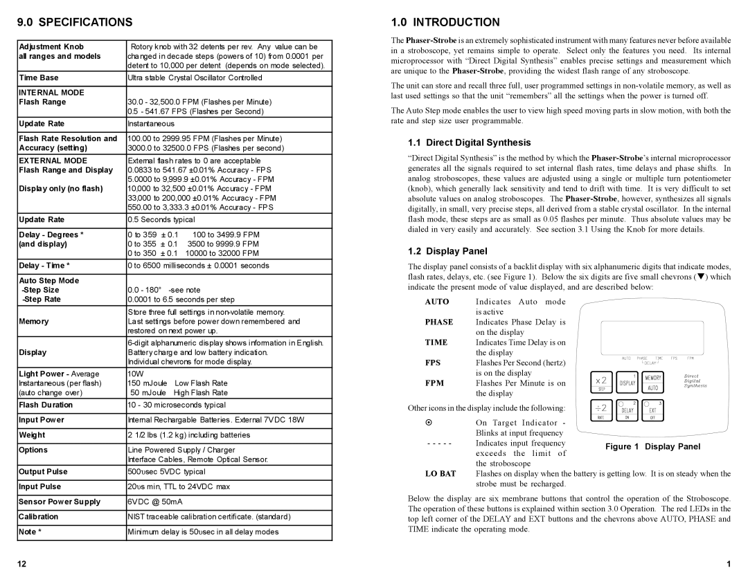
1.2 Display Panel
The display panel consists of a backlit display with six alphanumeric digits that indicate modes, flash rates, delays, etc. (see Figure 1). Below the six digits are five small chevrons (!) which indicate the present mode of value displayed, and are described below:
AUTO | Indicates Auto mode |
PHASE | is active |
Indicates Phase Delay is | |
TIME | on the display |
Indicates Time Delay is on | |
FPS | the display |
Flashes Per Second (hertz) | |
FPM | is on the display |
Flashes Per Minute is on | |
| the display |
Other icons in the display include the following:
! | On Target Indicator | - |
|
| Blinks at input frequency |
| |
- - - - - | Indicates input frequency | Figure 1 Display Panel | |
| exceeds the limit | of | |
|
| ||
LO BAT | the stroboscope |
|
|
Flashes on display when the battery is getting low. It is on steady when the | |||
| strobe must be recharged. |
| |
Below the display are six membrane buttons that control the operation of the Stroboscope. The operation of these buttons is explained within section 3.0 Operation. The red LEDs in the top left corner of the DELAY and EXT buttons and the chevrons above AUTO, PHASE and TIME indicate the operating mode.
12 | 1 |