Monarch 1071-4833-121 Preparation for USE, Power, Battery Disposal, Input / Output Connections

Models: 1071-4833-121

1 10
Download 10 pages 39.19 Kb
Page 6
Image 6
Figure 3 Input Connector Connection Detail
Common (GND)
Signal Input
+6V Out to Sensor
Signal Input
+6V Out to Sensor
Common (GND)

2.0 PREPARATION FOR USE

The Strobe may be hand held or mounted on a tripod or other user supplied bracket using the ¼-20 UNC bushing at the base of the handle.

2.1 Power

The Phaser-Strobehas internal rechargeable batteries and may also be powered by an optional external AC power supply. The unit should be charged before use (see section 8.3 Charging the Batteries), or can be run continuously from the AC mains with the optional power supply (PSC-3 or PSC-4, see section 8.4 External Power Supply/Charger). The Phaser-Strobecan operate continuously in excess of 60 minutes at 6000 flashes per minute from fully charged batteries. The strobe has a protection feature that prevents the strobe from operating if the battery voltage is low. This condition is indicated by no flash and the display starts blinking “LO BAT”. At this time the batteries must be recharged. The actual operating time of the stroboscope depends on the flash rate and duty cycle of operation. Slower flash rates increase the operating time.

To power the strobe with the external power supply/charger (PSC-3 or PSC-4):

1.Plug the power supply/charger cable into the recharger socket (located below the display panel behind the handle).

2.Plug the power supply/charger into an AC mains wall outlet.

3.Move the switch on the power supply/charger to “RUN”.

The stroboscope may operate in the “CHARGE” setting, but will in fact be drawing power from its internal batteries. An LED (light emitting diode) on the front of the power supply indicates the unit is on.

NOTE: If the batteries are depleted, they will need to be charged for about 10 minutes before trying to run the strobe from the power supply/charger.

WARNING: Do not leave the power supply/charger plugged into the Phaser- Strobe if there is no AC applied to the power supply/charger.

8.5 Battery Disposal

Prior to disposing of the Phaser-Strobe, the user must remove the sealed lead acid batteries. To do this, remove the lens, reflector and lamp as detailed in the Lamp Replacement section.

2.2 Input / Output Connections

The Phaser-Strobehas input and output jacks on the left side of the stroboscope (see Figure 2). These can be used for external triggering or synchronization (daisy chaining two or more strobes). These jacks accept 1/8" (3.5mm) phone plugs (input – stereo, output – mono). The jacks’ outer connection (barrel) is common and the inner or center connection is the signal (see Figure 3). The input jack also has a middle connection which provides power to an input sensor. The input and output are TTL compatible. Refer to section 10.0 Options interface cables.

! !

!"

Out In

Figure 2 Input/

Output Jacks

and Accessories for

This will expose 4 screws that must be removed so the reflector housing can be dismantled. There are four additional screws in the case half opposite the input and output jacks that must be removed. The case halves can now be separated, exposing the batteries. Remove the cables from the batteries and place tape over the battery terminals to prevent them from shorting. The batteries should be sent to a recycling center or returned to the factory. The rest of the parts may now be disposed of.

The optional ROS-5P (Remote Optical Sensor), MT-190P (Magnetic), IRS-5P (Infrared), or RLS-5P (Laser) sensors may also be used to trigger the unit.

NOTE: When using external sensors that are powered by the Phaser-Strobe, i.e. Remote Optical Sensor (ROS-5P), the sensor must be plugged in before the stroboscope is turned on, or the remote sensor may not be powered up.

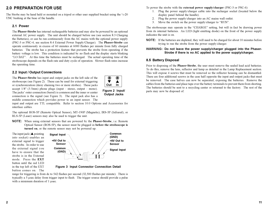
The input jack ("pointing into socket) enables an

external signal to trigger the strobe. In order to use the external signal you have to ensure that the

strobe is in the External mode. Press the EXT button until the red LED

in the top left of the EXT button comes on. The

range for triggering is from dc to 542 flashes per second (32,500 flashes per minute). There is typically a 5 µsec delay from trigger input to flash. The trigger source should provide a pulse with a minimum duration of 1 µsec.

2

11

Page 6
Image 6
Monarch 1071-4833-121 instruction manual Preparation for USE, Power, Battery Disposal, Input / Output Connections