Hands Free Kit
The location MUST NOT interfere with the vehicle’s air bag deployment.
Installing the Power Cable and Fuse Kit
Caution: Failure to follow these steps may cause the accessory not to work properly and may cause damage to the car kit.
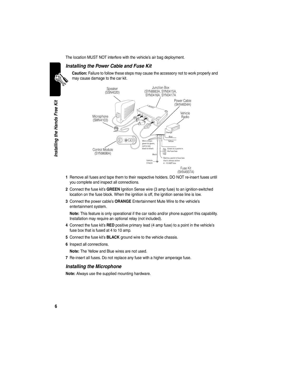
Speaker | Junction Box |
(SSN4020) | (SYN8883A, SYN0415A, |
| SYN0416A, SYN0417A |
| Power Cable |
| (SKN4834A) |
Microphone | Vehicle |
Radio | |
(SMN4103) |
|
Installing the
Control Module
(SYN9698A)
C
BWire crimps: green to green, red to red, black to black
Black
Vehicle
Chassis
Orange
Blue
Yellow
Green: to a point in the fuse box
Red: to a point in fuse box that is always active
4 - 10 AMP fuse
Fuse Kit
(SKN4937A)
1Remove all fuses and tape them to their respective holders. DO NOT
2Connect the fuse kit’s GREEN Ignition Sense wire (3 amp fuse) to an
3Connect the power cable’s ORANGE Entertainment Mute Wire to the vehicle’s entertainment system.
Note: This feature is only operational if the car radio and/or phone support this capability. Installation may require an optional relay (not included).
4Connect the fuse kit’s RED positive primary lead (4 amp fuse) to a point in the vehicle’s fuse box that is fused at 4 to 10 amp.
5Connect the fuse kit’s BLACK ground wire to the vehicle chassis.
6Inspect all connections.
Note: The Yellow and Blue wires are not used.
7
Installing the Microphone
Note: Always use the supplied mounting hardware.
6