MEMORY MAPS
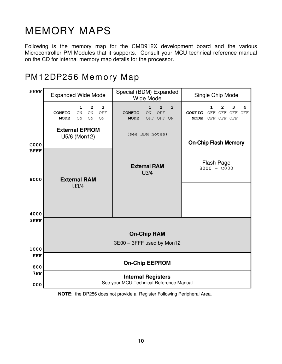
Following is the memory map for the CMD912X development board and the various Microcontroller PM Modules that it supports. Consult your MCU technical reference manual on the CD for internal memory map details for the processor.
PM12DP256 Memory Map
FFFF
C000 BFFF
8000
4000
3FFF
1000 FFF
800
7FF
000
Expanded Wide Mode | Special (BDM) Expanded | Single Chip Mode |
| |||||||||
Wide Mode |
|
| ||||||||||
|
|
|
|
|
|
|
|
|
| |||
| 1 | 2 | 3 |
| 1 | 2 | 3 |
| 1 | 2 | 3 | 4 |
CONFIG | ON | ON | OFF | CONFIG | ON | OFF |
| CONFIG | OFF OFF OFF OFF | |||
MODE | ON | ON | ON | MODE | OFF OFF ON | MODE | OFF OFF OFF |
| ||||
External EPROM | (see BDM notes) |
|
|
|
|
|
| |||||
U5/6 (Mon12) |
|
|
|
|
|
|
| |||||
|
|
|
|
| ||||||||
|
|
|
|
|
|
|
| |||||
|
|
|
|
|
|
|
|
|
|
| ||
|
|
|
| External RAM |
| Flash Page |
|
| ||||
|
|
|
|
| 8000 – C000 |
| ||||||
|
|
|
|
| U3/4 |
|
|
| ||||
|
|
|
|
|
|
|
|
|
|
|
| |
External RAM |
|
|
|
|
|
|
|
|
|
| ||
| U3/4 |
|
|
|
|
|
|
|
|
|
|
|
|
|
|
|
|
|
|
|
|
|
| ||
|
|
|
|
|
|
|
|
|
| |||
|
|
|
| 3E00 – 3FFF used by Mon12 |
|
|
|
|
| |||
|
|
|
|
|
|
|
|
|
|
| ||
|
|
|
|
|
|
|
|
|
| |||
|
|
|
|
|
|
|
|
|
|
| ||
|
|
|
| Internal Registers |
|
|
|
|
|
| ||
|
|
| See your MCU Technical Reference Manual |
|
|
|
| |||||
|
|
|
|
|
|
|
|
|
|
|
|
|
NOTE: the DP256 does not provide a Register Following Peripheral Area.
10