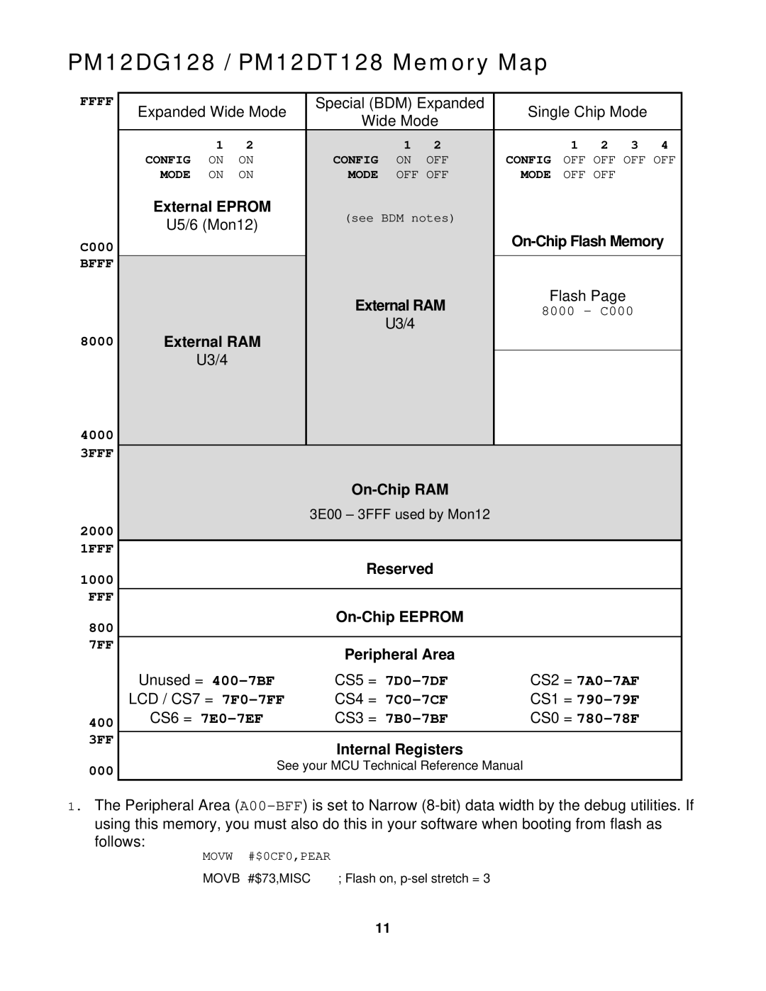
PM12DG128 / PM12DT128 Memory Map
FFFF
C000 BFFF
8000
4000
3FFF
2000
1FFF
1000 FFF
800
7FF
400
3FF
000
| Expanded Wide Mode | Special (BDM) Expanded | Single Chip Mode |
|
| |||||||
| Wide Mode |
|
| |||||||||
|
|
|
|
|
|
|
|
|
| |||
|
| 1 | 2 |
| 1 | 2 |
| 1 | 2 | 3 | 4 |
|
| CONFIG | ON | ON | CONFIG | ON | OFF | CONFIG | OFF OFF OFF OFF | ||||
| MODE | ON | ON | MODE | OFF OFF | MODE | OFF OFF |
|
|
| ||
| External EPROM | (see BDM notes) |
|
|
|
|
|
| ||||
| U5/6 (Mon12) |
|
|
|
|
|
| |||||
|
|
|
| |||||||||
|
|
|
|
|
|
| ||||||
|
|
|
|
|
|
|
|
|
|
| ||
|
|
|
| External RAM | Flash Page |
|
|
| ||||
|
|
|
| 8000 – C000 |
|
| ||||||
|
|
|
|
| U3/4 |
|
|
| ||||
|
|
|
|
|
|
|
|
|
|
|
| |
| External RAM |
|
|
|
|
|
|
|
|
| ||
|
| U3/4 |
|
|
|
|
|
|
|
|
|
|
|
|
|
|
|
|
|
|
|
|
| ||
|
|
|
|
|
|
|
|
|
| |||
|
|
|
| 3E00 – 3FFF used by Mon12 |
|
|
|
|
|
| ||
|
|
|
|
|
|
|
|
|
|
| ||
|
|
|
| Reserved |
|
|
|
|
|
| ||
|
|
|
|
|
|
|
|
|
|
| ||
|
|
|
|
|
|
|
|
|
| |||
|
|
|
|
|
|
|
|
|
|
| ||
|
|
|
| Peripheral Area |
|
|
|
|
|
| ||
| Unused = | CS5 = | CS2 = |
|
| |||||||
| LCD / CS7 = | CS4 = | CS1 = |
|
| |||||||
| CS6 = | CS3 = | CS0 = |
|
| |||||||
Internal Registers
See your MCU Technical Reference Manual
1.The Peripheral Area
follows:
MOVW #$0CF0,PEAR
MOVB #$73,MISC ; Flash on,
11