OPTION SWITCHES
CONFIG SWITCH
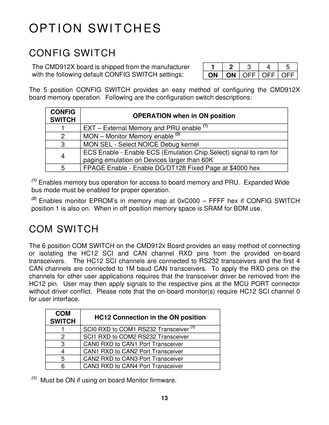
The CMD912X board is shipped from the manufacturer | 1 | 2 | 3 | 4 | 5 |
with the following default CONFIG SWITCH settings: | ON | ON | OFF | OFF | OFF |
The 5 position CONFIG SWITCH provides an easy method of configuring the CMD912X board memory operation. Following are the configuration switch descriptions:
CONFIG | OPERATION when in ON position | |
SWITCH | ||
| ||
1 | EXT – External Memory and PRU enable (1) | |
2 | MON – Monitor Memory enable (2) | |
3 | MON SEL - Select NOICE Debug kernel | |
4 | ECS Enable - Enable ECS (Emulation Chip Select) signal to ram for | |
paging emulation on Devices larger than 60K | ||
|
5FPAGE Enable - Enable DG/DT128 Fixed Page at $4000 hex
(1)Enables memory bus operation for access to board memory and PRU. Expanded Wide bus mode must be enabled for proper operation.
(2)Enables monitor EPROM’s in memory map at 0xC000 – FFFF hex if CONFIG SWITCH position 1 is also on. When in off position memory space is SRAM for BDM use.
COM SWITCH
The 6 position COM SWITCH on the CMD912x Board provides an easy method of connecting or isolating the HC12 SCI and CAN channel RXD pins from the provided
COM
HC12 Connection in the ON position
SWITCH
1SCI0 RXD to COM1 RS232 Transceiver (1)
2SCI1 RXD to COM2 RS232 Transceiver
3CAN0 RXD to CAN1 Port Transceiver
4CAN1 RXD to CAN2 Port Transceiver
5CAN2 RXD to CAN3 Port Transceiver
6CAN3 RXD to CAN4 Port Transceiver
(1)Must be ON if using on board Monitor firmware.
13