Interconnect Signals
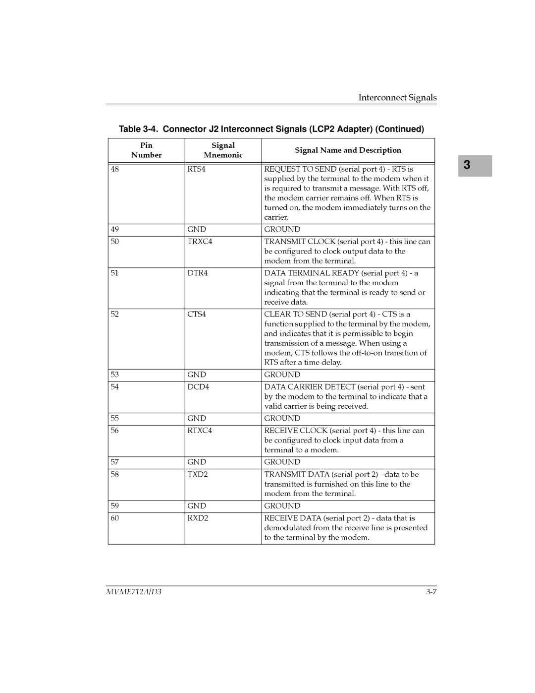
Table 3-4. Connector J2 Interconnect Signals (LCP2 Adapter) (Continued)
Pin | Signal | Signal Name and Description | |
Number | Mnemonic | ||
| |||
|
|
| |
|
|
| |
48 | RTS4 | REQUEST TO SEND (serial port 4) - RTS is | |
|
| supplied by the terminal to the modem when it | |
|
| is required to transmit a message. With RTS off, | |
|
| the modem carrier remains off. When RTS is | |
|
| turned on, the modem immediately turns on the | |
|
| carrier. | |
|
|
| |
49 | GND | GROUND | |
|
|
| |
50 | TRXC4 | TRANSMIT CLOCK (serial port 4) - this line can | |
|
| be conÞgured to clock output data to the | |
|
| modem from the terminal. | |
|
|
| |
51 | DTR4 | DATA TERMINAL READY (serial port 4) - a | |
|
| signal from the terminal to the modem | |
|
| indicating that the terminal is ready to send or | |
|
| receive data. | |
|
|
| |
52 | CTS4 | CLEAR TO SEND (serial port 4) - CTS is a | |
|
| function supplied to the terminal by the modem, | |
|
| and indicates that it is permissible to begin | |
|
| transmission of a message. When using a | |
|
| modem, CTS follows the | |
|
| RTS after a time delay. | |
|
|
| |
53 | GND | GROUND | |
|
|
| |
54 | DCD4 | DATA CARRIER DETECT (serial port 4) - sent | |
|
| by the modem to the terminal to indicate that a | |
|
| valid carrier is being received. | |
|
|
| |
55 | GND | GROUND | |
|
|
| |
56 | RTXC4 | RECEIVE CLOCK (serial port 4) - this line can | |
|
| be conÞgured to clock input data from a | |
|
| terminal to a modem. | |
|
|
| |
57 | GND | GROUND | |
|
|
| |
58 | TXD2 | TRANSMIT DATA (serial port 2) - data to be | |
|
| transmitted is furnished on this line to the | |
|
| modem from the terminal. | |
|
|
| |
59 | GND | GROUND | |
|
|
| |
60 | RXD2 | RECEIVE DATA (serial port 2) - data that is | |
|
| demodulated from the receive line is presented | |
|
| to the terminal by the modem. | |
|
|
|
3 |
MVME712A/D3 |
