Electrical Connections RF Antenna Connections | |
|
|
4.2RF Antenna Connections
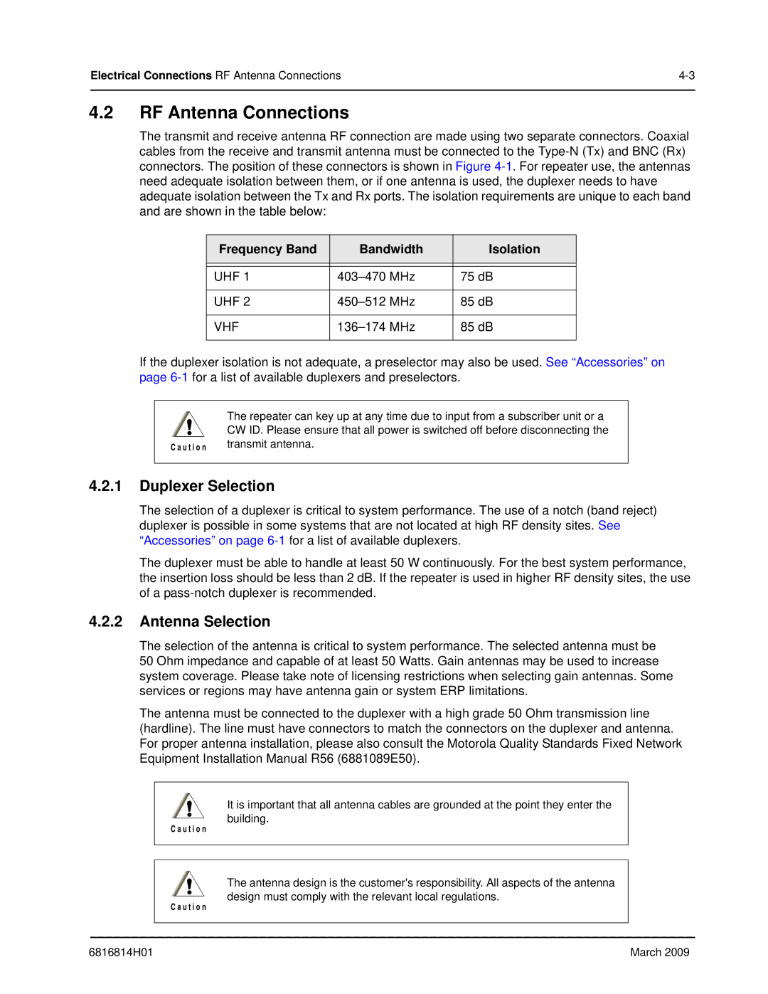
The transmit and receive antenna RF connection are made using two separate connectors. Coaxial cables from the receive and transmit antenna must be connected to the
Frequency Band | Bandwidth | Isolation |
|
|
|
|
|
|
UHF 1 | 75 dB | |
|
|
|
UHF 2 | 85 dB | |
|
|
|
VHF | 85 dB | |
|
|
|
If the duplexer isolation is not adequate, a preselector may also be used. See “Accessories” on page
! | The repeater can key up at any time due to input from a subscriber unit or a |
CW ID. Please ensure that all power is switched off before disconnecting the | |
C a u t i o n | transmit antenna. |
|
|
4.2.1Duplexer Selection
The selection of a duplexer is critical to system performance. The use of a notch (band reject) duplexer is possible in some systems that are not located at high RF density sites. See “Accessories” on page
The duplexer must be able to handle at least 50 W continuously. For the best system performance, the insertion loss should be less than 2 dB. If the repeater is used in higher RF density sites, the use of a
4.2.2Antenna Selection
The selection of the antenna is critical to system performance. The selected antenna must be
50 Ohm impedance and capable of at least 50 Watts. Gain antennas may be used to increase system coverage. Please take note of licensing restrictions when selecting gain antennas. Some services or regions may have antenna gain or system ERP limitations.
The antenna must be connected to the duplexer with a high grade 50 Ohm transmission line (hardline). The line must have connectors to match the connectors on the duplexer and antenna. For proper antenna installation, please also consult the Motorola Quality Standards Fixed Network Equipment Installation Manual R56 (6881089E50).
!It is important that all antenna cables are grounded at the point they enter the building.
C a u t i o n
!The antenna design is the customer's responsibility. All aspects of the antenna design must comply with the relevant local regulations.
C a u t i o n
6816814H01 | March 2009 |
