UPort 1200/1400/1600 Series User’s Manual | Driver Installation |
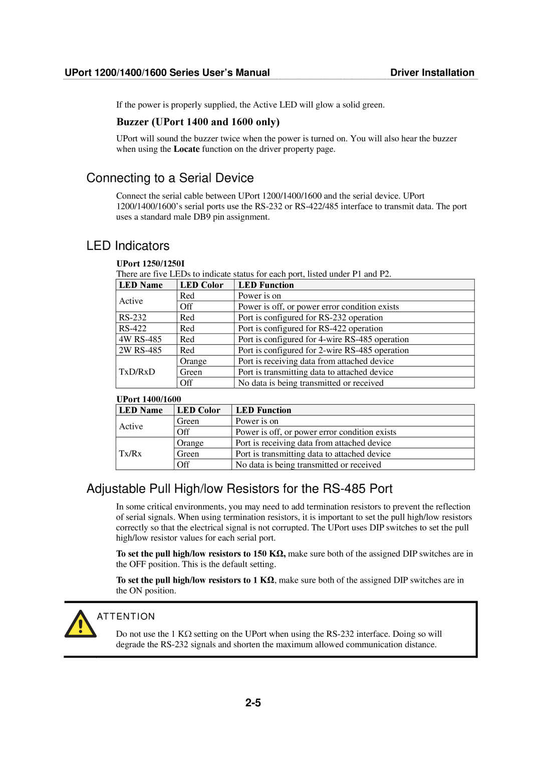
If the power is properly supplied, the Active LED will glow a solid green.
Buzzer (UPort 1400 and 1600 only)
UPort will sound the buzzer twice when the power is turned on. You will also hear the buzzer when using the Locate function on the driver property page.
Connecting to a Serial Device
Connect the serial cable between UPort 1200/1400/1600 and the serial device. UPort 1200/1400/1600’s serial ports use the
LED Indicators
UPort 1250/1250I
There are five LEDs to indicate status for each port, listed under P1 and P2.
LED Name | LED Color | LED Function | |||
Active | Red | Power is on | |||
Off | Power is off, or power error condition exists | ||||
|
| ||||
Red | Port is configured for | ||||
Red | Port is configured for | ||||
4W | Red | Port is configured for | |||
2W | Red | Port is configured for | |||
TxD/RxD | Orange | Port is receiving data from attached device | |||
Green | Port is transmitting data to attached device | ||||
|
| Off | No data is being transmitted or received | ||
UPort 1400/1600 |
| ||||
LED Name |
| LED Color |
| LED Function | |
Active |
| Green |
| Power is on | |
| Off |
| Power is off, or power error condition exists | ||
|
|
| |||
Tx/Rx |
| Orange |
| Port is receiving data from attached device | |
| Green |
| Port is transmitting data to attached device | ||
|
| Off |
| No data is being transmitted or received | |
Adjustable Pull High/low Resistors for the RS-485 Port
In some critical environments, you may need to add termination resistors to prevent the reflection of serial signals. When using termination resistors, it is important to set the pull high/low resistors correctly so that the electrical signal is not corrupted. The UPort uses DIP switches to set the pull high/low resistor values for each serial port.
To set the pull high/low resistors to 150 KΩ, make sure both of the assigned DIP switches are in the OFF position. This is the default setting.
To set the pull high/low resistors to 1 KΩ, make sure both of the assigned DIP switches are in the ON position.
ATTENTION
Do not use the 1 KΩ setting on the UPort when using the
