Fiber Driver
EM316E3 & EM316E3SF
Theory of Operation
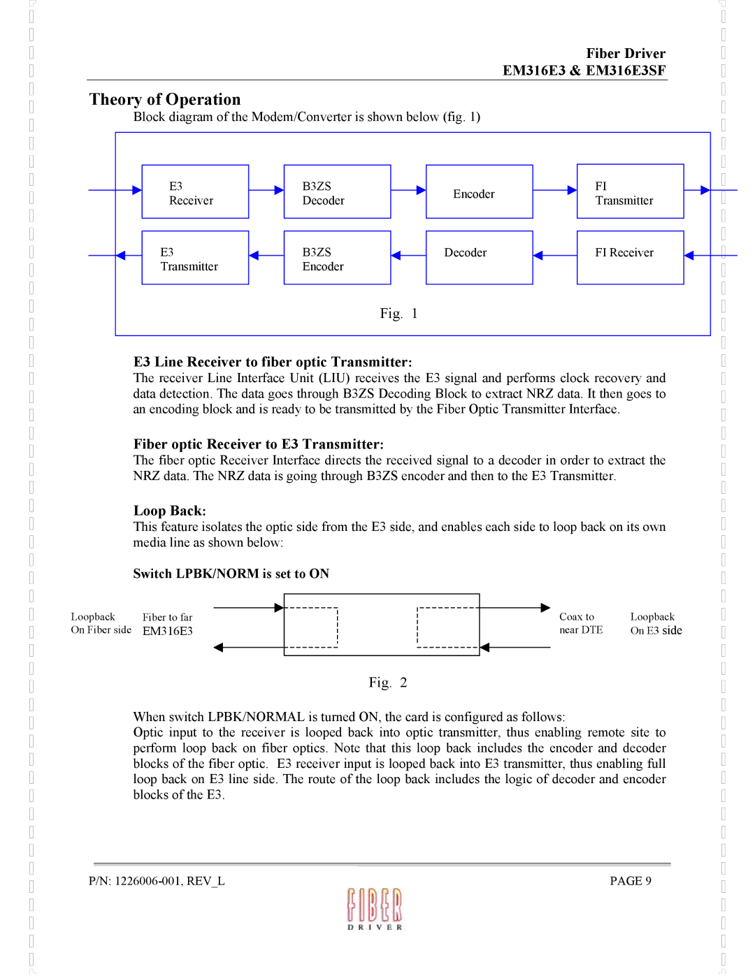
Block diagram of the Modem/Converter is shown below (fig. 1)
E3 | B3ZS | Encoder | FI | |
Receiver | Decoder | Transmitter | ||
| ||||
E3 | B3ZS | Decoder | FI Receiver | |
Transmitter | Encoder |
|
| |
| Fig. | 1 |
|
E3 Line Receiver to fiber optic Transmitter:
The receiver Line Interface Unit (LIU) receives the E3 signal and performs clock recovery and data detection. The data goes through B3ZS Decoding Block to extract NRZ data. It then goes to an encoding block and is ready to be transmitted by the Fiber Optic Transmitter Interface.
Fiber optic Receiver to E3 Transmitter:
The fiber optic Receiver Interface directs the received signal to a decoder in order to extract the NRZ data. The NRZ data is going through B3ZS encoder and then to the E3 Transmitter.
Loop Back:
This feature isolates the optic side from the E3 side, and enables each side to loop back on its own media line as shown below:
Switch LPBK/NORM is set to ON
Loopback On Fiber side
Fiber to far
EM316E3
Coax to | Loopback |
near DTE | On E3 side |
|
|
Fig. 2
When switch LPBK/NORMAL is turned ON, the card is configured as follows:
Optic input to the receiver is looped back into optic transmitter, thus enabling remote site to perform loop back on fiber optics. Note that this loop back includes the encoder and decoder blocks of the fiber optic. E3 receiver input is looped back into E3 transmitter, thus enabling full loop back on E3 line side. The route of the loop back includes the logic of decoder and encoder blocks of the E3.
P/N: | PAGE 9 |