If you experienced resistance rolling the unit, either when repositioning the shift lever from 6 to R2 or when attempting to move the machine with the drive control released, adjust the drive control immediately. To adjust, proceed as follows:
•Loosen the nylock nut on the drive control cable and unthread the cable one full turn. See Figure
•Recheck adjustment.
•Retighten the nylock nut to secure the cable when correct adjustment is reached.
NOTE: For more details, refer to Drive Control Adjust- ment in the Adjustment Section of this manual.
Auger Control
Check the adjustment of the auger control as follows:
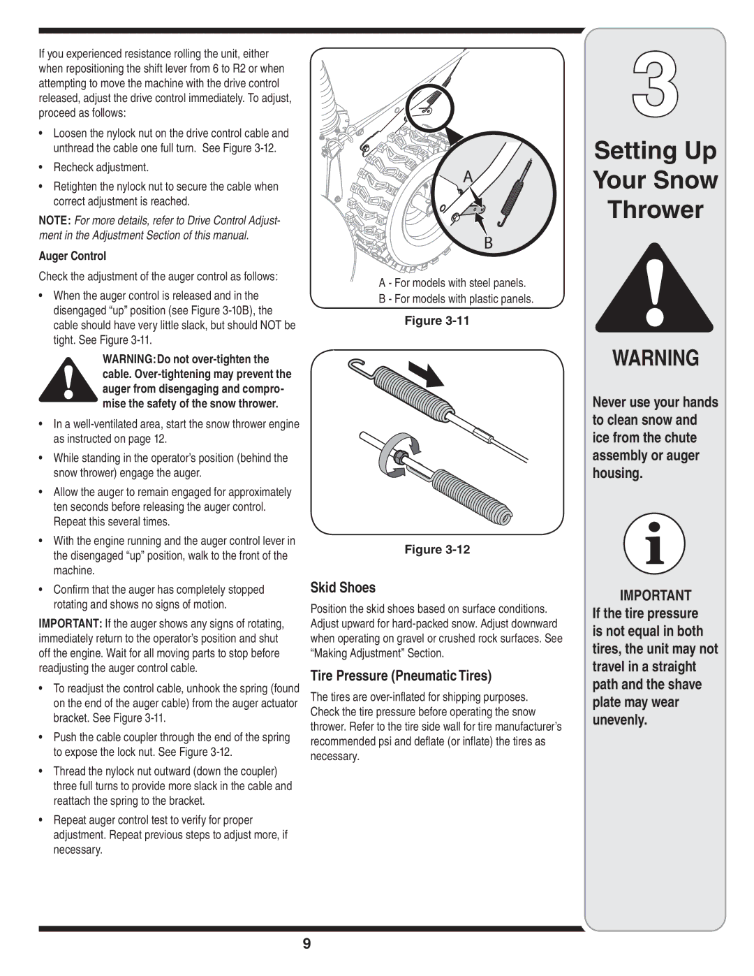
•When the auger control is released and in the disengaged “up” position (see Figure
WARNING:Do not
•In a
•While standing in the operator’s position (behind the snow thrower) engage the auger.
•Allow the auger to remain engaged for approximately ten seconds before releasing the auger control. Repeat this several times.
•With the engine running and the auger control lever in the disengaged “up” position, walk to the front of the machine.
•Confirm that the auger has completely stopped rotating and shows no signs of motion.
IMPORTANT: If the auger shows any signs of rotating, immediately return to the operator’s position and shut off the engine. Wait for all moving parts to stop before readjusting the auger control cable.
•To readjust the control cable, unhook the spring (found on the end of the auger cable) from the auger actuator bracket. See Figure
•Push the cable coupler through the end of the spring to expose the lock nut. See Figure
•Thread the nylock nut outward (down the coupler) three full turns to provide more slack in the cable and reattach the spring to the bracket.
•Repeat auger control test to verify for proper adjustment. Repeat previous steps to adjust more, if necessary.
A
B
A - For models with steel panels.
B - For models with plastic panels.
Figure
Figure
Skid Shoes
Position the skid shoes based on surface conditions. Adjust upward for
Tire Pressure (Pneumatic Tires)
The tires are
3
Setting Up
Your Snow
Thrower
WARNING
Never use your hands to clean snow and ice from the chute assembly or auger housing.
IMPORTANT If the tire pressure is not equal in both tires, the unit may not travel in a straight path and the shave plate may wear unevenly.
9
