Chapter 1 – Product Description and Specifications
Interfaces
The Wireless MultiModem has several interfaces:
LED function indicating operating status
External antenna (via SMA connector)
Serial and control link (via 15 pins SUB D)
Power supply (via 2.5mm miniature power jack)
SIM card holder
LEDs
| LED Indicators |
TD | Transmit Data. Lit when modem is transmitting data. |
RD | Receive Data. Lit when modem is receiving data. |
CD | Carrier Detect. Lit when data connection has been established. |
LS | Line Status. |
| Continuous “on” state indicates that the wireless modem is not registered on the network. |
| Flashing state indicates registration on network. |
| Off state. Modem is off (not ready) or in download mode. |
TR | Terminal Ready. Commonly called “Data Terminal Ready.” This is a readiness signal from the PC. |
PWR | Power. Indicates presence of DC power when lit. |
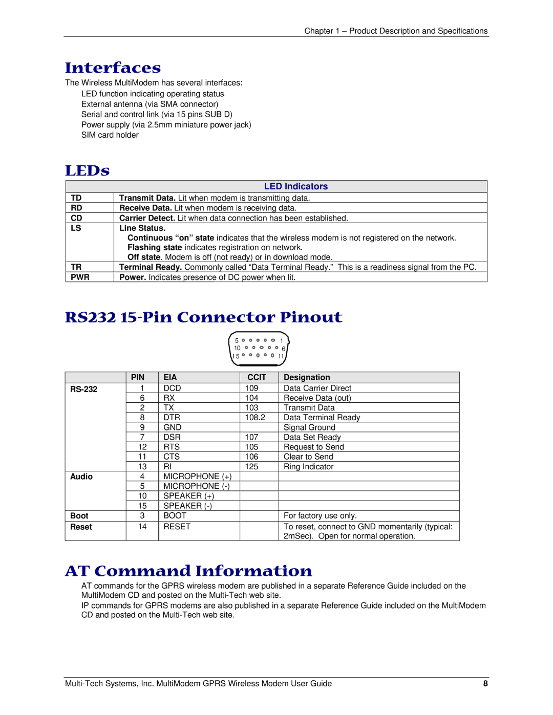
RS232 15-Pin Connector Pinout
|
| 5 |
| 1 |
|
| 10 |
| 6 |
|
| 1 5 |
| 11 |
|
|
|
|
|
|
|
|
|
|
| PIN | EIA | CCIT | Designation |
| 1 | DCD | 109 | Data Carrier Direct |
| 6 | RX | 104 | Receive Data (out) |
| 2 | TX | 103 | Transmit Data |
| 8 | DTR | 108.2 | Data Terminal Ready |
| 9 | GND |
| Signal Ground |
| 7 | DSR | 107 | Data Set Ready |
| 12 | RTS | 105 | Request to Send |
| 11 | CTS | 106 | Clear to Send |
| 13 | RI | 125 | Ring Indicator |
Audio | 4 | MICROPHONE (+) |
|
|
| 5 | MICROPHONE |
|
|
| 10 | SPEAKER (+) |
|
|
| 15 | SPEAKER |
|
|
Boot | 3 | BOOT |
| For factory use only. |
Reset | 14 | RESET |
| To reset, connect to GND momentarily (typical: |
|
|
|
| 2mSec). Open for normal operation. |
AT Command Information
AT commands for the GPRS wireless modem are published in a separate Reference Guide included on the MultiModem CD and posted on the
IP commands for GPRS modems are also published in a separate Reference Guide included on the MultiModem CD and posted on the
8 |
