Model AR13D
Diesel engine exhaust and some
AR13D RIDE-ON Roller Proposition 65WARNING
Page
AR13D RIDE-ON Roller -TABLE of Contents
Order via Fax Dealers Only
Parts Ordering Procedures
Best Deal! Order via Internet Dealers Only
Structure that does not provide ample free flow air
AR13D RIDE-ON Roller Safety Message Alert Symbols
Always wear approved eye and hearing protection
AR13D RIDE-ON Roller Safety Message Alert Symbols
Always wear approved respiratory protection
Contact with hot components can cause serious burns
AR13D RIDE-ON Roller Rules for Safe Operation
Engine or pump
Always wear seat belts
AR13D RIDE-ON Roller Rules for Safe Operation
Always know the location of the nearest fire extinguisher
Never stand below roller when it is being lifted
Machine Safety Decals
AR13D RIDE-ON Roller Operation and Safety Decals
AR13D RIDE-ON Roller Operation and Safety Decals
AR13D RIDE-ON Roller Specifications Roller
Model Briggs & Stratton DM 850D
AR13D RIDE-ON Roller Specifications Engine
Side View
AR13D RIDE-ON Roller Dimensions
AR13D RIDE-ON Roller General Information
Power Plant
Tipping Rollovers
AR13D RIDE-ON Roller General Information
Roller Components
AR13D RIDE-ON Roller Roller Components
SteeringWheel Use this wheel to steer the roller
AR13D RIDE-ON Roller Roller Components
AR13D RIDE-ON Roller Roller Components
Motor oil
AR13D RIDE-ON Roller Engine Components
+12 VDC electrical system
Cold weather conditions
Engine Oil Check
AR13D RIDE-ON Roller Inspection
Before Starting
Fuel Check
AR13D RIDE-ON Roller Inspection
Hydraulic Oil Check
Lic oil to the recommended operating level
AR13D RIDE-ON Roller Inspection
Initial Start-up Instructions Starting
AR13D RIDE-ON Roller Initial START-UP
Sprinkler Controls
Parking Brake
Vibration Button
Perform roller maintenance as indicated by and Table
AR13D RIDE-ON Roller Maintenance
Maintenance
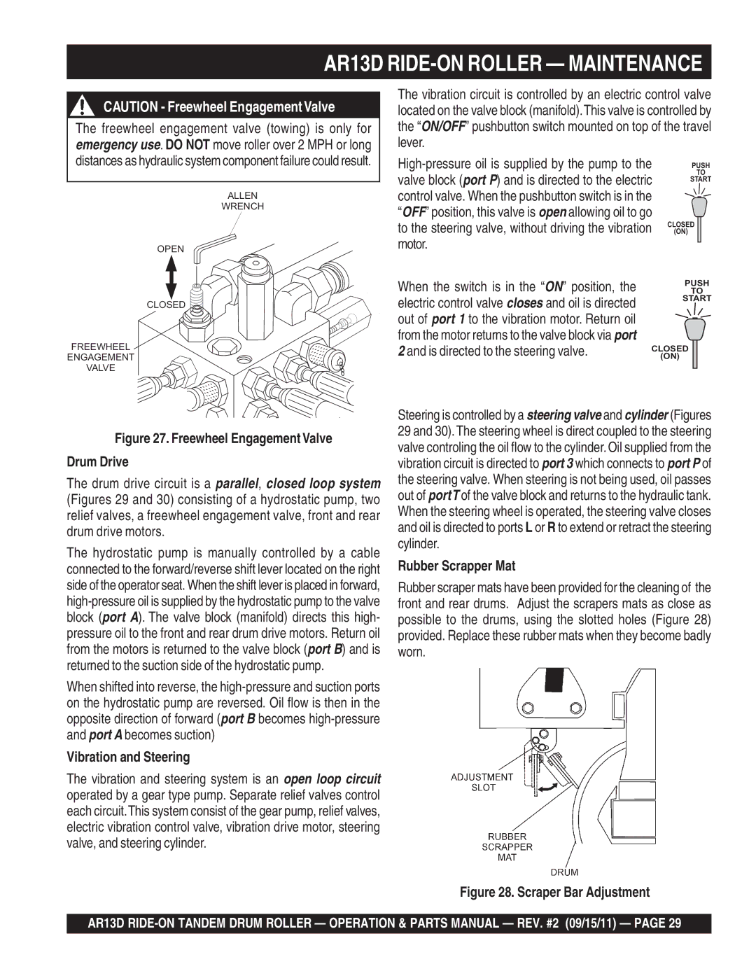
Freewheel Engagement Valve
Hydraulic Oil System
Is directed to the steering valve
AR13D RIDE-ON Roller Maintenance
Vibration and Steering
Rubber Scrapper Mat
Forward/Reverse Hydraulic Pressure Test
Adjust engine RPM 3,500 +/- 50 RPM
Vibration Circuit PressureTest
Steering Pressure Test
Forward/Reverse ReliefValves Drive Adjustment
Removing and Replacing Hydrostatic Pump
Front and Rear Drum Removal and Disassembly
Removing and Replacing Vibration/Steering Pump
Drums and Main Frame
Front-Right Drum Removal
Front-Left Drum Removal
Rear Drum Removal/Installation
Alternator/Regulator
Neutral Safety Switch
Roller Storage
AR13D RIDE-ON Roller Preparation for LONG-TERM Storage
Manifold Test Ports
AR13D RIDE-ON Roller Manifoldtest Ports
Hydraulic System Diagram
AR13D RIDE-ON Roller Hydraulic System Diagram
AR13D Roller Electricwiring Diagram
Page
Hydraulic Hose Connections
AR13D RIDE-ON Roller Hydraulic Hose Connections
AR13D RIDE-ON Roller Hydraulic Hose Connections
Manifold
Roller Troubleshooting
AR13D RIDE-ON Roller -TROUBLESHOOTING Roller
AR13D RIDE-ON Roller -TROUBLESHOOTING Engine
Engine Troubleshooting
AR13D RIDE-ON Roller -TROUBLESHOOTING Engine
Page
Xxxxx only Not Used on
Explanation of Code in Remarks Column
Description
AR13D RIDE-ON Roller Suggested Spare Parts
Name Plate and Decals
AR13D RIDE-ON Roller Name Plate and Decals
AR13D RIDE-ON Roller Name Plate and Decals
Front Drum Assy
AR13D RIDE-ON Roller Front Drum Assy
Front Roller
Housing Bearing
Bearing
RING, Retaining
Exciter Assy
AR13D RIDE-ON Roller Exciter Assy
HOUSING, Bearing Left
HOUSING, Bearing Right
SCREW, Allen 5/16
Seal
Rear Drum & Chassis Assy
AR13D RIDE-ON Roller Rear Drum & Chassis Assy
AR13D RIDE-ON Roller Rear Drum & Chassis Assy
AR13D RIDE-ON Roller Covers and Frame Articulation Lock Assy
Rear Water Tank Cover
Covers and Frame Articulation Lock Assy
Floor Plate
ARM, Floor Cover
Hood and Rear Panel Assy
AR13D RIDE-ON Roller Hood and Rear Panel Assy
HINGE, Slotted
Hood
Latch KIT Hood
Front Chassis
Steering Column and Hydraulic Articulation Assy
AR13D Steering Column and Hydraulic Articulation Assy
HARNESS, Wiring
SWITCH, Starter
Elbow Fitting
CYLINDER, Steering
Articulation ARM
AR13D RIDE-ON Roller Articulation ARM Assy
Flat Washer 3/4
ROD END
ROD, Direction Stabilizer
Hydraulic Drive Pump Assy
AR13D RIDE-ON Roller Hydraulic Drive Pump Assy
ADAPTER, Steering Pump
PUMP, Steering
Hydraulic Pump
Shift Lever
Manifold and Hydraulic OIL Filter Assy
AR13D RIDE-ON Roller Manifold and Hydraulic OIL Filter Assy
Hydraulic Tank CAP
Chassis AR13D
Straight Fitting 3/4
Filter
Fuel Tank & OIL Drain Hose Assy
AR13D RIDE-ON Roller Fueltank & OIL Drain Hose Assy
Fuel Tank
PAD, Rubber Tank
BRACKET, Fuel Tank Support
CAP, Fuel W/GAUGE
AR13D RIDE-ON Roller Watertank Assy
Water Tank Assembly Assy
Water Tank CAP
Water Tank
Clamp
Elbow PVC
Engine Mounting Assy
AR13D RIDE-ON Roller Engine Mounting Assy
452# 835034
MOUNT, Engine
Muffler Assy
AR13D RIDE-ON Roller Muffler Assy
Mount PLATE, Muffler
Bolt
Muffler Base Extension
ELBOW, Exhaust
AIR Cleaner Assy
AR13D RIDE-ON Roller AIR Cleaner Assy
ELEMENT, AIR Filter
AIR Intake Hose
Hose AIR Inlet
Radiator Assy
AR13D RIDE-ON Roller Radiator Assy
Mount Radiator Overflow
Trim EDGE1 X
NUT 1/4-20 Nylon Lock
Radiator Mounting KIT
Throttle Assy
AR13D RIDE-ON Roller -THROTTLE Assy
Travel Lever FWD/REV
Cable Throttle Assembly
CABLE, FORWARD/REVERSE
Joint Ball
Brake Control Assy
AR13D RIDE-ON Roller Brake Control Assy
Brake Link
LEVER, Brake
Bell Crank
BRACKET, Brake
Battery Assy
AR13D RIDE-ON Roller Battery Assy
AR13D RIDE-ON Roller Battery Assy
Scraper Assy
AR13D RIDE-ON Roller Scraper Assy
SCRAPER, Rubber
SCRAPER, Support
Plate Backing
NUT, Lock 1/2 NC
Freight Policy
Terms and Conditions of Sale
Page
HERE’S HOW to GET Help