DCA180SSK specifications
The Multiquip DCA180SSK is a powerful and versatile generator specifically designed for construction sites, events, and other demanding applications. This model boasts an impressive power output of 180 kVA, making it suitable for a wide range of electrical needs. Its reliable performance combined with advanced features makes it a preferred choice for professionals in various industries.One of the standout characteristics of the DCA180SSK is its robust, diesel-powered engine. This generator is equipped with a reliable Yanmar diesel engine, known for its durability and efficiency. The engine not only ensures consistent power delivery but also meets stringent emission regulations, making it environmentally friendly. The unit features a fuel-efficient design capable of running for extended periods, which reduces the frequency of refueling and associated downtime.
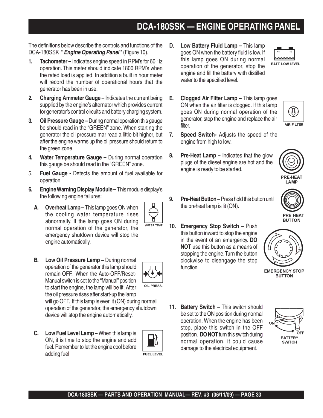
The DCA180SSK generator is also engineered for ease of use. It incorporates a user-friendly control panel that provides clear visibility of operational parameters, including voltage output, frequency, and fuel levels. This intuitive interface allows operators to monitor the generator’s performance effortlessly.
Another significant technological advancement in the DCA180SSK is its advanced sound attenuation features. The generator is built within a durable, weather-protective enclosure that minimizes noise levels to enhance worksite safety and compliance with local regulations. This feature not only benefits job sites in urban environments but also improves working conditions for operators and workers alike.
Portability is another key attribute. The DCA180SSK is designed with a compact structure, making it easy to transport and position on-site. The addition of lifting points facilitates quick and safe relocation, while its rugged chassis ensures it can withstand the rigors of construction environments.
This generator also incorporates numerous safety features, including automatic shut-off protocols for low oil pressure and high temperature, enhancing operator safety and extending engine life. With its blend of technology, durability, and user-centric design, the Multiquip DCA180SSK generator provides dependable power for any demanding application, ensuring that work proceeds smoothly, efficiently, and safely.

