ga-9.7HE specifications
The Multiquip GA-9.7HE is a high-performance generator that caters to the diverse needs of construction sites, industrial applications, and outdoor events. Engineered with robust features and advanced technologies, it stands out as a reliable power source in various environments.One of the standout features of the GA-9.7HE is its powerful engine. Powered by a Honda gasoline engine, this generator delivers an impressive output of 9.7 kW, making it suitable for powering multiple tools and equipment simultaneously. The engine is designed for efficiency and durability, ensuring long operational hours with minimal maintenance requirements.
An integral component of the GA-9.7HE is its advanced inverter technology. This technology allows for cleaner, stable power output that is ideal for sensitive electronics and equipment. Whether it's powering construction tools or providing backup for electronics at an outdoor event, the inverter capability ensures optimal performance without risking damage to sensitive devices.
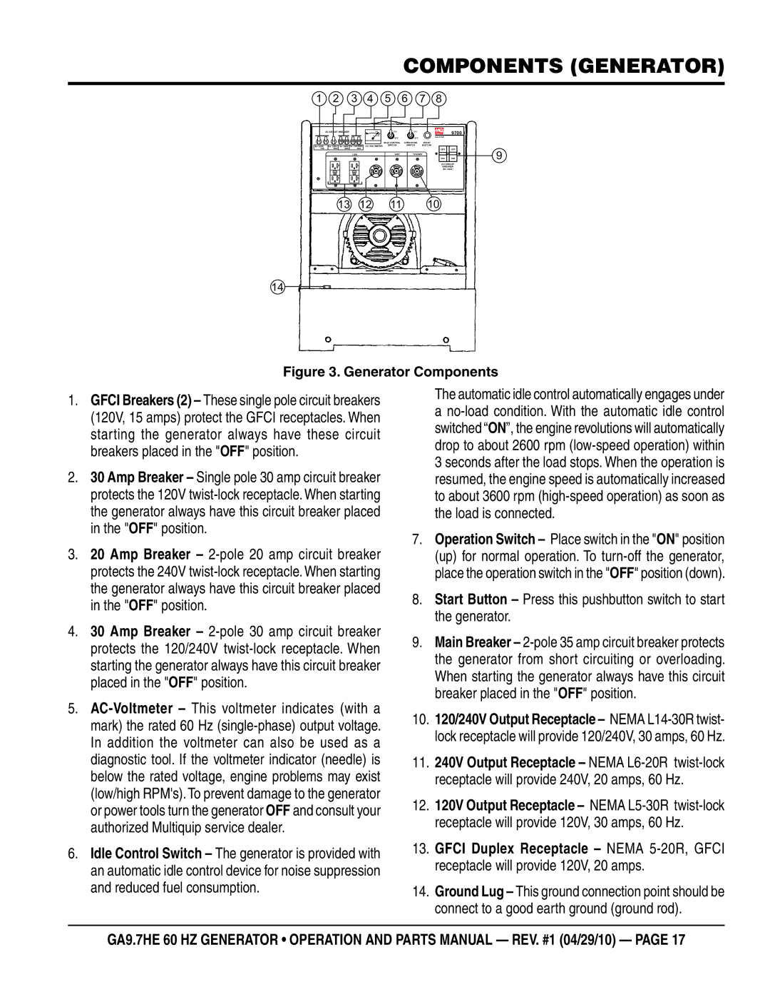
Additionally, the GA-9.7HE features a user-friendly control panel that provides easy access to essential functions. The control panel includes circuit breakers, output indicators, and start/stop controls, allowing operators to manage the generator efficiently. This ease of use is critical for ensuring seamless operation, especially in fast-paced work environments.
Portability is another key aspect of the GA-9.7HE. It is designed with a compact frame and comes equipped with heavy-duty wheels, making it easy to transport across job sites or during events. The lightweight construction also contributes to its mobility, allowing users to quickly reposition the generator as needed.
Safety features have not been overlooked in the GA-9.7HE. It includes automatic low-oil shutdown and circuit breaker protection, which help prevent engine damage and electrical issues. These safety measures are essential for maintaining the longevity of the generator and ensuring safe operation in various applications.
With a focus on reliability, efficiency, and versatility, the Multiquip GA-9.7HE is an excellent choice for those seeking a dependable power solution. Its combination of a powerful engine, advanced inverter technology, user-friendly design, and safety features makes it a valuable asset for contractors, event planners, and anyone in need of portable power.

