components
9 |
| 2 | 3 | 6 |
| 1 |
| 5 | |
| 4 | 4 | ||
|
|
12 | 11 |
|
7
8
10
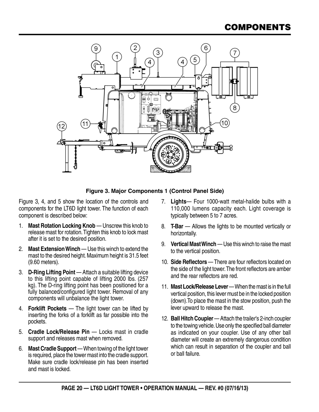
Figure 3. Major Components 1 (Control Panel Side)
Figure 3, 4, and 5 show the location of the controls and components for the LT6D light tower. The function of each component is described below:
1.Mast Rotation Locking Knob — Unscrew this knob to release mast for rotation. Tighten this knob to lock mast after it is set to the desired position.
2.Mast ExtensionWinch — Use this winch to extend the mast to the desired height. Maximum height is 31.5 feet (9.60 meters).
3.
4.Forklift Pockets — The light tower can be lifted by inserting the forks of a forklift as far possible into the pockets.
5.Cradle Lock/Release Pin — Locks mast in cradle support and releases mast when removed.
6.Mast Cradle Support — When towing of the light tower is required, place the tower mast into the cradle support. Make sure cradle lock/release pin has been inserted and mast is locked.
7.Lights— Four
8.
9.Vertical MastWinch — Use this winch to raise the mast to the vertical position.
10.Side Reflectors — There are four reflectors located on the side of the light tower.The front reflectors are amber and the rear reflectors are red.
11.Mast Lock/Release Lever — When the mast is in the full vertical position, this lever must be in the locked position (down).To place the mast in the stow position, push the lever upward to release the mast.
12.Ball Hitch Coupler — Attach the trailer's
page 20 — LT6D LIGHT TOWER • operation manual — rev. #0 (07/16/13)