digital controller panel
3 | 1 |
|
|
|
|
|
|
| 4 |
13 |
|
|
|
|
|
|
|
| 11 |
|
|
|
|
|
|
|
|
| |
|
| Microprocessor Engine Controller |
|
| |||||
|
|
| MEC 20 |
|
|
|
| ||
|
| Vavg | Aavg | Freq |
|
| |||
| ALARM | 600 |
| 508 | 60.0 | READY |
| ||
|
|
|
|
|
|
|
| ||
| SHUTDOWN | SILENCE | LAMP TEST | RESET | SPEED SIGNAL |
| |||
|
| EXIT | DECREMENT | INCREMENT | ENTER |
|
| ||
14 |
|
|
|
|
|
|
|
| 12 |
|
|
|
|
|
|
|
|
| |
|
|
|
|
|
|
|
| EMERGENCY | 5 |
2 |
|
|
|
|
|
|
|
| |
|
|
|
|
|
| LOAD | STOP |
| |
|
| RUN |
| OFF | AUTO |
|
| ||
|
|
| TEST |
|
| ||||
|
|
|
|
|
|
|
| 10 | |
|
|
|
|
|
|
|
|
| |
6 |
|
|
|
|
|
|
|
|
|
|
|
|
|
|
|
|
|
| 9 |
7 |
| FREQUENCY |
|
|
|
| VOLTAGE |
| 8 |
|
| ADJUST |
|
|
|
| ADJUST |
|
|
| 15 |
|
|
|
|
|
| 16 |
|
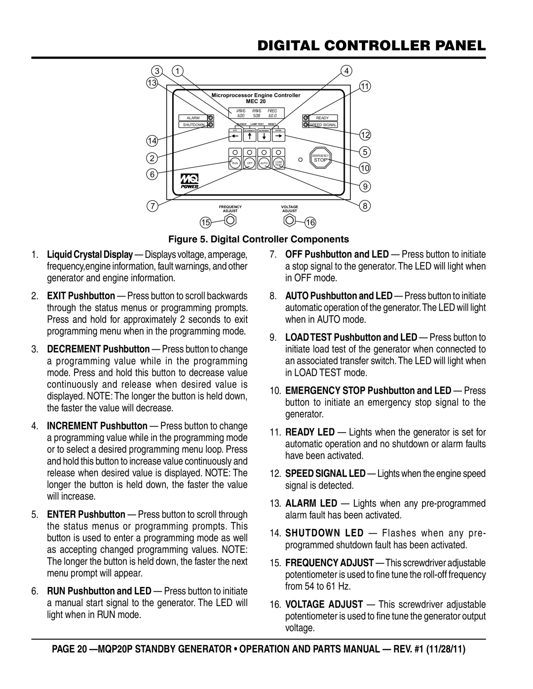
Figure 5. Digital Controller Components
1.Liquid Crystal Display — Displays voltage, amperage, frequency,engine information, fault warnings, and other generator and engine information.
2.EXIT Pushbutton — Press button to scroll backwards through the status menus or programming prompts. Press and hold for approximately 2 seconds to exit programming menu when in the programming mode.
3.DECREMENT Pushbutton — Press button to change a programming value while in the programming mode. Press and hold this button to decrease value continuously and release when desired value is displayed. NOTE: The longer the button is held down, the faster the value will decrease.
4.INCREMENT Pushbutton — Press button to change a programming value while in the programming mode or to select a desired programming menu loop. Press and hold this button to increase value continuously and release when desired value is displayed. NOTE: The longer the button is held down, the faster the value will increase.
5.ENTER Pushbutton — Press button to scroll through the status menus or programming prompts. This button is used to enter a programming mode as well as accepting changed programming values. NOTE: The longer the button is held down, the faster the next menu prompt will appear.
6.RUN Pushbutton and LED — Press button to initiate a manual start signal to the generator. The LED will light when in RUN mode.
7.OFF Pushbutton and LED — Press button to initiate a stop signal to the generator. The LED will light when in OFF mode.
8.AUTO Pushbutton and LED — Press button to initiate automatic operation of the generator.The LED will light when in AUTO mode.
9.LOADTEST Pushbutton and LED — Press button to initiate load test of the generator when connected to an associated transfer switch. The LED will light when in LOAD TEST mode.
10.EMERGENCY STOP Pushbutton and LED — Press button to initiate an emergency stop signal to the generator.
11.READY LED — Lights when the generator is set for automatic operation and no shutdown or alarm faults have been activated.
12.SPEED SIGNAL LED — Lights when the engine speed signal is detected.
13.ALARM LED — Lights when any
14.SHUTDOWN LED — Flashes when any pre- programmed shutdown fault has been activated.
15.FREQUENCY ADJUST — This screwdriver adjustable potentiometer is used to fine tune the
16.VOLTAGE ADJUST — This screwdriver adjustable potentiometer is used to fine tune the generator output voltage.
page 20