COMPONENTS
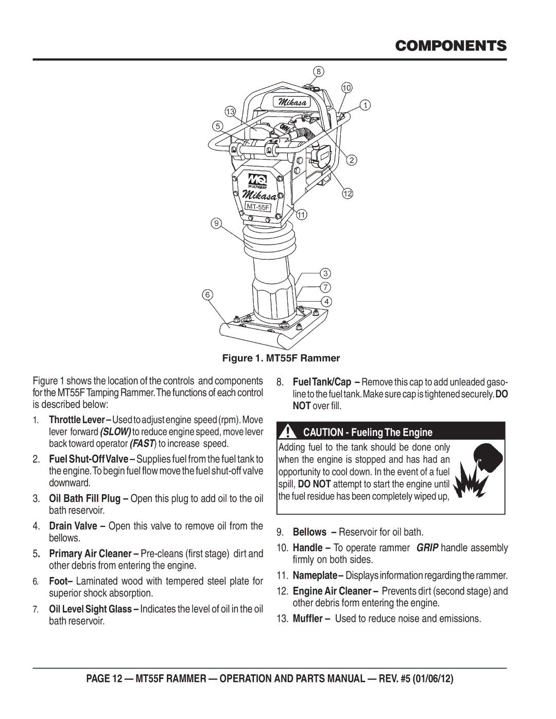
Figure 1. MT55F Rammer
Figure 1 shows the location of the controls and components for the MT55F Tamping Rammer.The functions of each control is described below:
1.Throttle Lever
2.Fuel
3.Oil Bath Fill Plug – Open this plug to add oil to the oil bath reservoir.
4.Drain Valve – Open this valve to remove oil from the bellows.
5. Primary Air Cleaner –
6.Foot– Laminated wood with tempered steel plate for superior shock absorption.
7.Oil Level Sight Glass – Indicates the level of oil in the oil bath reservoir.
8.FuelTank/Cap – Remove this cap to add unleaded gaso- line to the fuel tank.Make sure cap is tightened securely.DO NOT over fill.
CAUTION - Fueling The Engine
Adding fuel to the tank should be done only when the engine is stopped and has had an opportunity to cool down. In the event of a fuel spill, DO NOT attempt to start the engine until the fuel residue has been completely wiped up,
9.Bellows – Reservoir for oil bath.
10.Handle – To operate rammer GRIP handle assembly firmly on both sides.
11.Nameplate– Displaysinformationregardingtherammer.
12.Engine Air Cleaner – Prevents dirt (second stage) and other debris form entering the engine.
13.Muffler – Used to reduce noise and emissions.
PAGE 12 — MT55F RAMMER — OPERATION AND PARTS MANUAL — REV. #5 (01/06/12)