ST-3050D SUB. PUMP/CTRL. BOX — 3Ø PWR. INSTALLATION (CB200)
1.The three phase input power cord should have four wires. Each wire is color coded. The colors are RED, WHITE, BLACK and GREEN.
2.Remove the
3-PHASE POWER INSTALLATION (OUTPUTTO PUMP)
1.The three phase output power cord should have four wires. Each wire is color coded. The colors are RED, WHITE, BLACK and GREEN.
2.Remove the
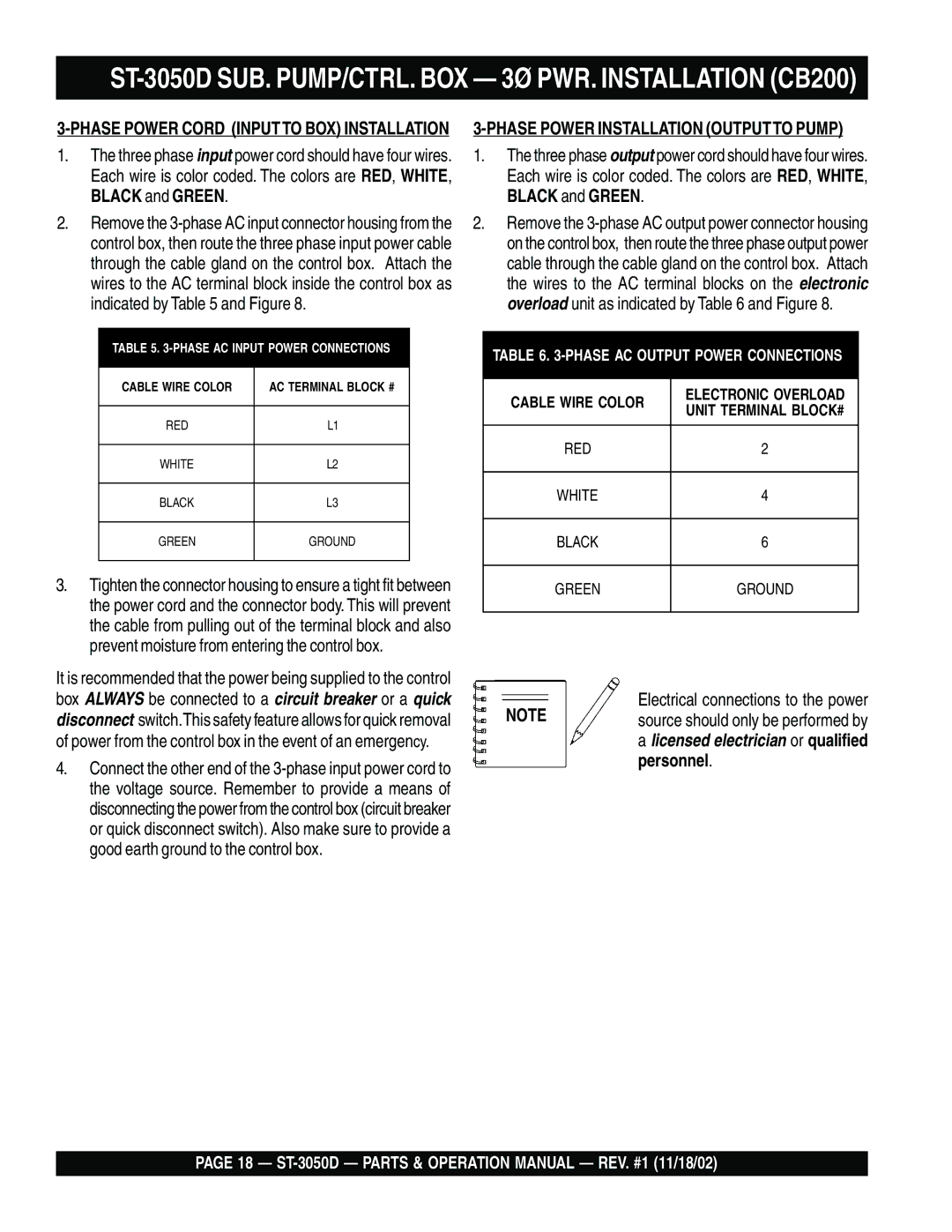
TABLE 5. 3-PHASE AC INPUT POWER CONNECTIONSS
CABLE WIRE COLOR | AC TERMINAL BLOCK # |
|
|
RED | L1 |
|
|
WHITE | L2 |
|
|
BLACK | L3 |
|
|
GREEN | GROUND |
|
|
3.Tighten the connector housing to ensure a tight fit between the power cord and the connector body. This will prevent the cable from pulling out of the terminal block and also prevent moisture from entering the control box.
It is recommended that the power being supplied to the control box ALWAYS be connected to a circuit breaker or a quick disconnect switch.This safety feature allows for quick removal of power from the control box in the event of an emergency.
4.Connect the other end of the
TABLE 6.
CABLE WIRE COLOR | ELECTRONIC OVERLOAD | |
UNIT TERMINAL BLOCK# | ||
| ||
|
| |
RED | 2 | |
|
| |
WHITE | 4 | |
|
| |
BLACK | 6 | |
|
| |
GREEN | GROUND | |
|
|
Electrical connections to the power
NOTE source should only be performed by a licensed electrician or qualified
personnel.
PAGE 18 —