start-up
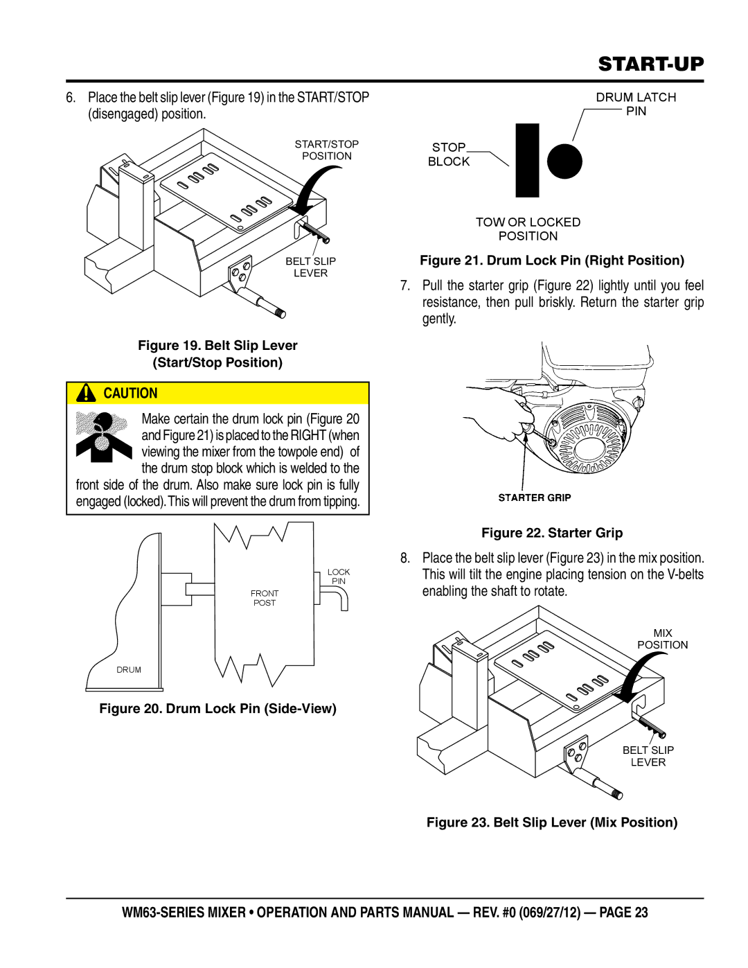
6.Place the belt slip lever (Figure 19) in the START/STOP (disengaged) position.
START/STOP
STOP
DRUM LATCH ![]() PIN
PIN
POSITION
BELT SLIP
LEVER
Figure 19. Belt Slip Lever
(Start/Stop Position)
![]() CAUTION
CAUTION
Make certain the drum lock pin (Figure 20
and Figure 21) is placed to the RIGHT (when
![]()
![]()
![]()
![]() viewing the mixer from the towpole end) of the drum stop block which is welded to the front side of the drum. Also make sure lock pin is fully
viewing the mixer from the towpole end) of the drum stop block which is welded to the front side of the drum. Also make sure lock pin is fully
engaged (locked).This will prevent the drum from tipping.
LOCK
PIN
FRONT
POST
DRUM
Figure 20. Drum Lock Pin (Side-View)
BLOCK
TOW OR LOCKED
POSITION
Figure 21. Drum Lock Pin (Right Position)
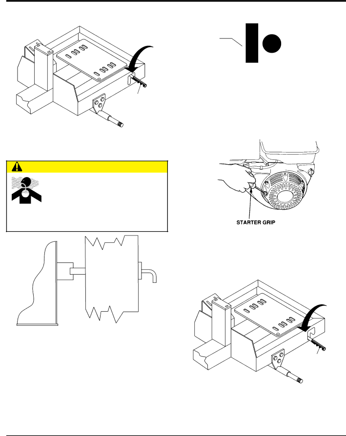
7.Pull the starter grip (Figure 22) lightly until you feel resistance, then pull briskly. Return the starter grip gently.
Figure 22. Starter Grip
8.Place the belt slip lever (Figure 23) in the mix position. This will tilt the engine placing tension on the
MIX
POSITION
BELT SLIP
LEVER