Cultivator
MURRAY, INC. Two Year Limited Warranty
OWNER’S Information
Responsibility of the Owner
Safety Rules
Operating Safety
Fuel Safety
Safe Operation Practices for Cultivator
Safe Storage
Repair / Adjustments Safety
Such as wheel weights, counterweights, and the like
International Symbols
Slow Fast Fuel Oil Choke OFF Half Choke Full Choke
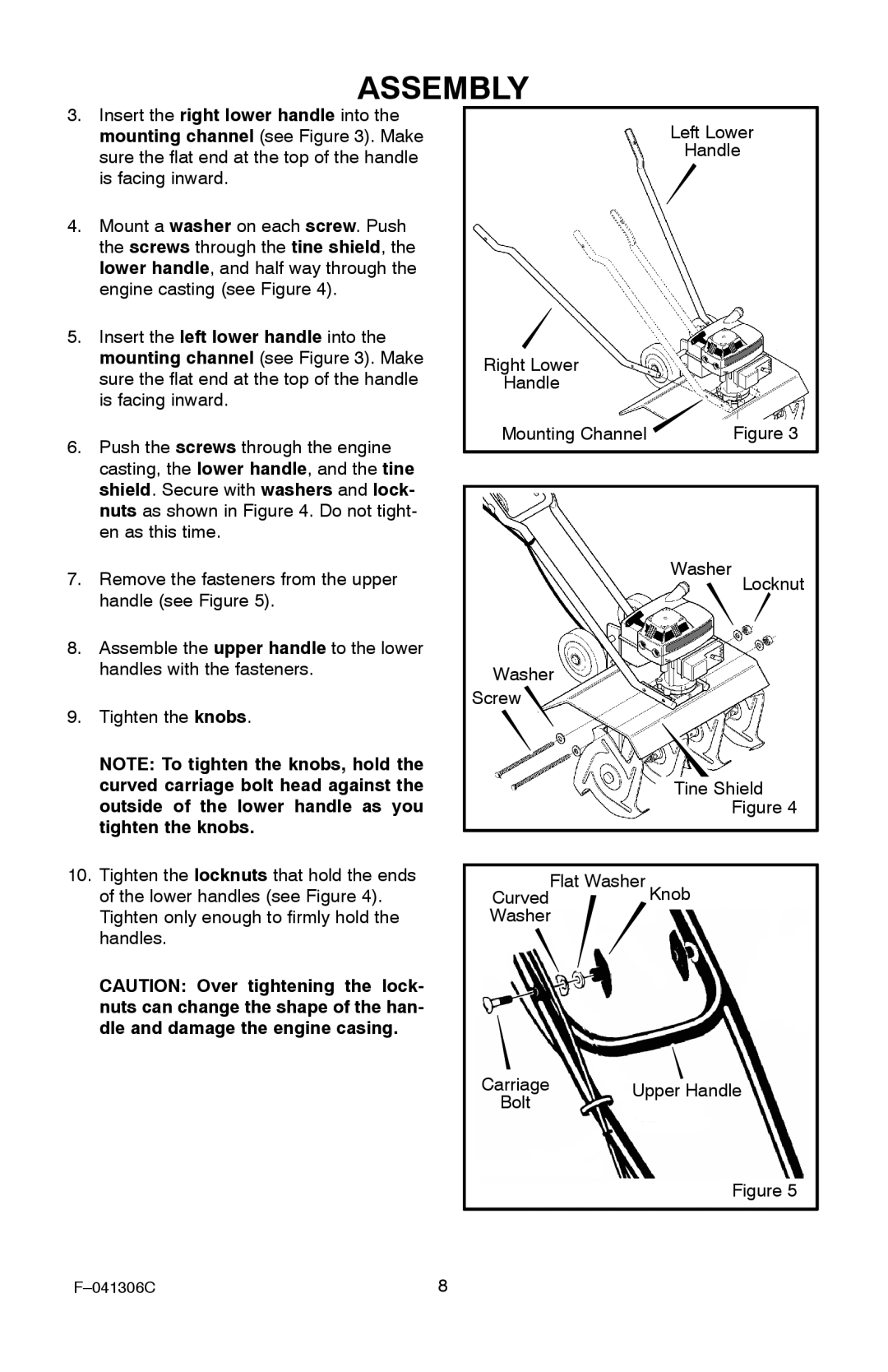
Assembly
Assembly Parts Packed Separately in Carton
HOW to Remove the Cultivator from the Carton
HOW to Assemble the Handle
Outside of the lower handle as you
Tighten the knobs
Tighten the locknuts that hold the ends
Lower handles see Figure
Assembly
Checklist
EYE Protection
Operation
Know Your Cultivator
HOW to USE the Cultivator
HOW to Operate the Cultivator
How To Stop The Cultivator
How To Set The Depth
Before Starting the Engine
How To Prepare The Engine
How To Mix The Fuel Mixture
HOW to Start the Engine
Shut-Off Switch Recoil Starter Handle Air Cleaner
These areas
No Choke Half Choke Full Choke
Hints for Depth Stake or Wheel Adjustment
Cultivating Tips
Light cultivation with moderate growth To 2 inches depth
Seed bed preparation 4 to 6 inches depth
Maintenance
Product Specifications
Customer Responsibilities
General Recommendations
Lubrication
Remove the air vent screw see Figure
Before installing the spark plug, coat
Threads lightly with oil for easy re
Check the spark plug every 25 hours. Re
Ment spark plug
Service and Adjustment
HOW to Remove and Install the Tines
Tine Installation
Tine Removal
Engine
Storage
Cultivator
Trouble Shooting Chart
Trouble Cause Correction
Model 11052x4NC
323392C
318848C
Transmission
Includes Key Nos , 485 and four Key Nos
323393A
Tine Assy. Outer RH
KEY Description
323396B
Includes Key No + Includes Key No
319375C
Lower Handle RH +
Wire Assembly, Kill Switch
HOW to Order Repair Parts
MURRAY, INC. Lawn Mower Central Parts Distributors
MURRAY, INC. Garantie limitée de deux ans
Informations DE L’UTILISATEUR
Responsabilités DU Propriétaire
Consignes DE Sécurité
Règles de sécurité pour l’utilisation du cultivateur
Avant toute utilisation
Précautions pour le carburant
Sécurité d’entreposage
Sécurité des réparations et du réglage
Éloignez toute personne De la zone de travail
Lent Rapide Carburant
Starter fermé Mi-starter Plein starter
Montage
Déballage DU Cultivateur DE SON Carton
Montage DE LA Poignée
Rant le montage du cultivateur
Supérieur
Attache-câble
Liste DE Vérification
Roues de déplacement Abaisser les
Utilisation
Connaissance DU Cultivateur
Protection Oculaire
Mode D’EMPLOI DU Cultivateur
Conduite DU Cultivateur
Arrêt du cultivateur
Réglage de la profondeur
Avant DE Démarrer LE Moteur
Préparation du moteur
Composition du mélange de carburant
Mélange dosage 24 SI Métrique
Éviter de toucher ces parties
Démarrage DU Moteur
Starter fermé Mi starter Plein fermé
Conseils Pour LE Labourage
Conseils Pour LE Réglage DES Roues
Recommandations Générales
Entretien
Responsibilités DE L’ACHETEUR
Caractéristiques Produit
Retirez la vis de purge d’air voir Figure
Remontez la vis de purge d’air
Rondelle en feutre Graisseur Arbre des lames
Retirez les lames de l’arbre
Placement de la bougie
Vérifiez l’écartement des électrodes
Entretien ET Réglage
Démontage ET Montage DES Lames
Démontage des lames
Montage des lames
Motobineuse
Entreposage
Moteur
Panne Cause Réparation
Commande DE Pièces Détachées
Boundry, Canyon, Clearwater Elmore, Gem, Idaho, Kooten
Garantía Limitada de Dos Años de MURRAY, INC
Información Para EL Propietario
Responsabilidad DEL Propietario
Normas DE Seguridad
Normas de seguridad para la operación de la cultivadora
Antes de usar la unidad
Seguridad con el combustible
Hay
Almacenamiento seguro
Reparación / Ajustes seguros
Marcha lenta Marcha rápida Combustible
Cebador Apagado Cebado medio Cebado completo
Ensamblaje
Ensamblaje Partes Empacadas POR Separado EN LA Caja
Cómo Sacar LA Cultivadora DE LA Caja
Cómo Ensamblar EL Mango
Perno de Mango
Mango inferior Izquierdo Derecho Guía de montaje
Perilla
Figura Conjunto de
Amarre de cables
Lista DE Comprobación
Protección Para LOS Ojos
Operación
Conozca SU Cultivadora
Cómo Usar LA Cultivadora
Cómo Operar LA Cultivadora
Cómo detener la cultivadora
Cómo ajustar la profundidad
Antes DE Hacer Arrancar EL Motor
Cómo preparar el motor
Cómo preparar la mezcla de combustible
Proporción de SI. métrico
Control de cebado ahogador
Cómo Hacer Arrancar EL Motor
Nota No trate de cebar un motor ca- liente o tibio
Consejos Para Cultivar
Especificaciones DEL Producto
Mantenimiento
Responsabilidades DEL Cliente
Saque el tornillo del escape de aire Figura
De aire
De aceite, el eje de los dientes
Jía hasta lograr un par de apriete de
Servicio Y Ajuste
Cómo Desmontar Y Montar LOS Dientes
Desmontaje de los dientes
Instalación de los dientes
Motor
Almacenamiento
Cultivadora
Problema Causa Solución
Tabla DE Localizacion DE Averias
Nota
Nota
Cómo Hacer UN Pedido DE Piezas DE Repuesto