ASSEMBLY
HOW TO ASSEMBLE THE CONTROLS TO THE HANDLE
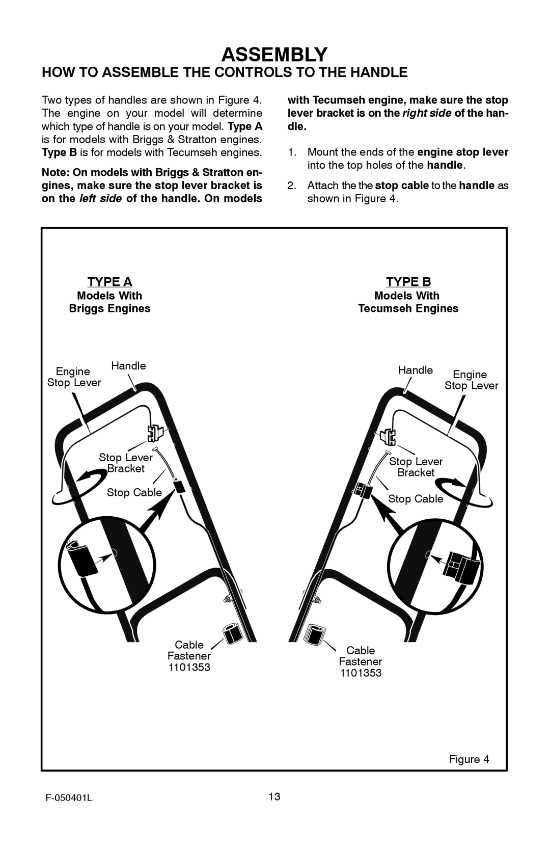
Two types of handles are shown in Figure 4. The engine on your model will determine which type of handle is on your model. Type A is for models with Briggs & Stratton engines. Type B is for models with Tecumseh engines.
Note: On models with Briggs & Stratton en- gines, make sure the stop lever bracket is on the left side of the handle. On models
with Tecumseh engine, make sure the stop lever bracket is on the right side of the han- dle.
1.Mount the ends of the engine stop lever into the top holes of the handle.
2.Attach the the stop cable to the handle as shown in Figure 4.
TYPE A |
| TYPE B |
| |
Models With |
| Models With |
| |
Briggs Engines |
| Tecumseh Engines | ||
Engine | Handle |
| Handle | Engine |
|
| |||
Stop Lever |
|
| Stop Lever | |
| Stop Lever |
| Stop Lever |
|
| Bracket |
|
| |
|
| Bracket |
| |
|
|
|
| |
| Stop Cable |
| Stop Cable |
|
|
|
|
| |
|
| Cable | Cable |
|
|
| Fastener |
| |
|
| Fastener |
| |
|
| 1101353 |
| |
|
| 1101353 |
| |
|
|
|
| |
|
|
|
| Figure 4 |
|
| 13 |
| |