
KW 500 specifications
The Musical Fidelity KW 500 is a high-performance integrated amplifier that is widely recognized for its exceptional sound quality and advanced technology. This amplifier is a perfect blend of power, precision, and musicality, making it a favorite among audiophiles and music enthusiasts.One of the most notable features of the KW 500 is its power output. With a robust 500 watts per channel into 8 ohms, it can drive even the most demanding speakers with ease. This power is not just about volume; it translates into a dynamic range that allows for the subtle nuances of music to shine through, delivering an immersive listening experience. The KW 500 is designed to deliver an authoritative bass response, crystal-clear mids, and a smooth treble, creating a balanced sound signature across various genres.
The KW 500 incorporates advanced Class A/B amplification technology, providing the best of both worlds—efficiency and sound quality. This type of amplification ensures that the amplifier operates at optimal temperatures while delivering a warm, rich sound. The design features high-quality components, including large capacitors and a robust power supply, which contribute to its overall performance and reliability.
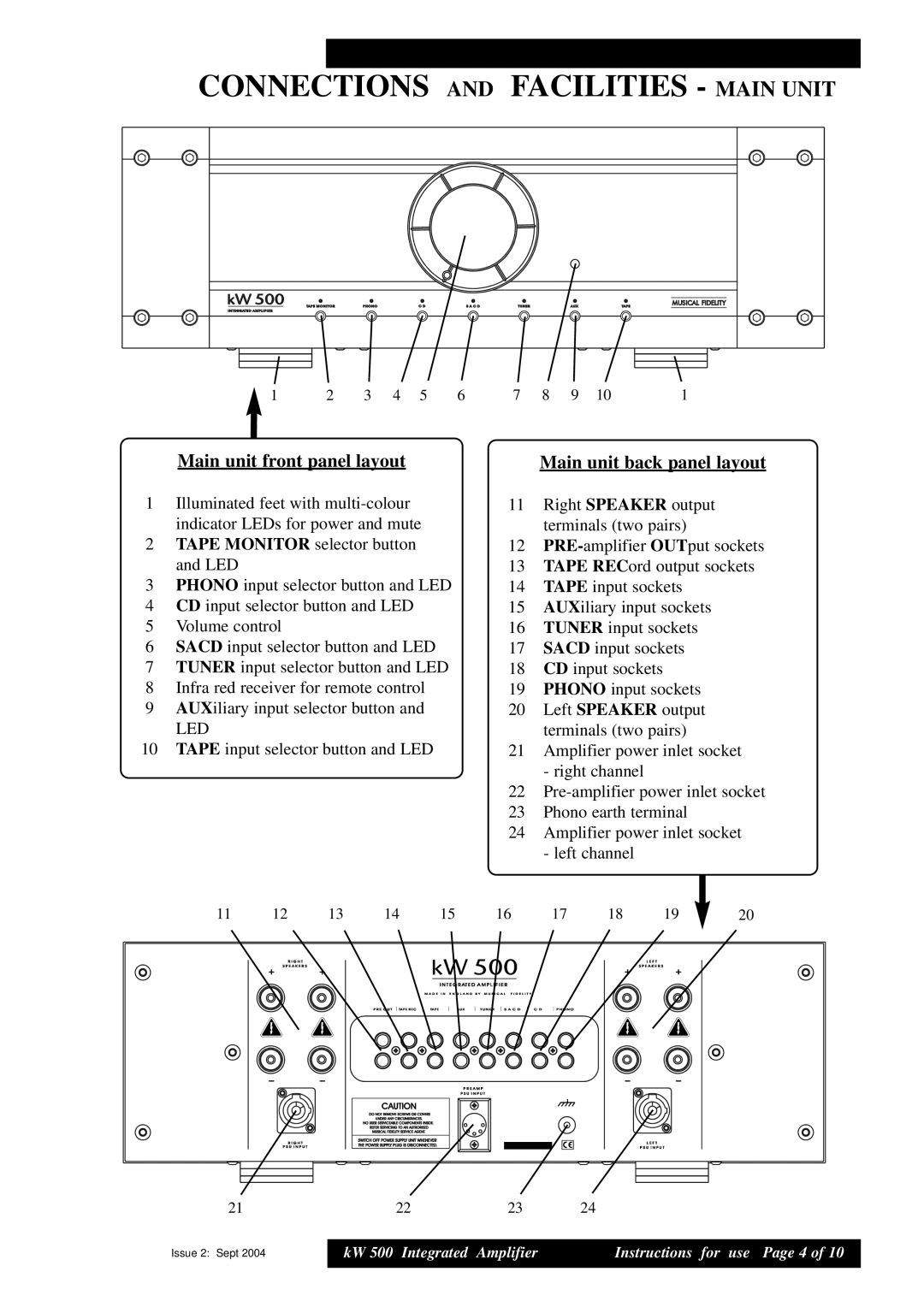
Another key feature of the KW 500 is its impressive array of input options. It comes equipped with multiple analog inputs, including balanced XLR and unbalanced RCA connections, as well as a dedicated phono stage for vinyl enthusiasts. This versatility allows users to connect various audio sources, from digital devices to turntables, facilitating a seamless listening experience.
The KW 500 also includes built-in active crossover technology, enabling it to perform exceptionally well within multi-amplification systems. This feature allows for precise control over the frequency distribution, ensuring that each driver in a speaker system operates optimally. This technology is particularly beneficial for audiophiles who seek to tailor their sound systems to achieve the best possible audio fidelity.
Moreover, the KW 500 is constructed with a heavy-duty chassis that minimizes vibrations and interference, further enhancing audio performance. Its minimalist design not only looks elegant but also serves functional purposes, ensuring that the components remain isolated for the best sound reproduction.
In summary, the Musical Fidelity KW 500 stands out with its powerhouse performance, advanced technologies, and versatility. Its combination of high output power, premium components, and thoughtful design makes it a top choice for those seeking a superior audio experience in an integrated amplifier. Whether you're listening to your favorite vinyl records or streaming high-resolution audio, the KW 500 is built to elevate your musical enjoyment to new heights.