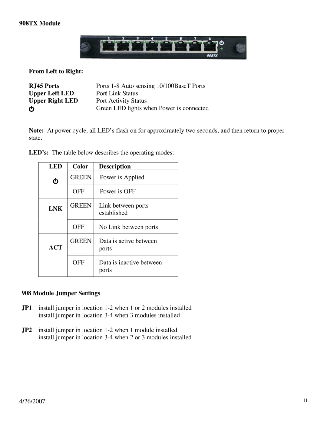
908TX Module
From Left to Right: |
|
RJ45 Ports | Ports |
Upper Left LED | Port Link Status |
Upper Right LED | Port Activity Status |
| Green LED lights when Power is connected |
Note: At power cycle, all LED’s flash on for approximately two seconds, and then return to proper state.
LED’s: The table below describes the operating modes:
LED | Color | Description |
| GREEN | Power is Applied |
|
|
|
| OFF | Power is OFF |
|
|
|
LNK | GREEN | Link between ports |
| established | |
|
| |
|
|
|
| OFF | No Link between ports |
|
|
|
ACT | GREEN | Data is active between |
| ports | |
|
|
|
| OFF | Data is inactive between |
|
| ports |
|
|
|
908 Module Jumper Settings
JP1 install jumper in location
JP2 install jumper in location
4/26/2007 | 11 |