DIN-Rail Mounting
Install the unit in a standard DIN-Rail. Recess the unit to allow at least 5” of horizontal clearance for fiber optic cable bend radius (2” for TX models). Note: This unit may be mounted horizontally or vertically.
To install the unit to 35mm industrial DIN-Rail - Place the top edge of the included mounting bracket on the back of the unit against the top flange of the DIN-Rail at a 15° angle. Rotate the bottom of the u nit to the back (away from you) until it snaps into place.
To remove the unit from the 35 mm industrial DIN-Rails - Apply downward force to the unit until it disengages from the bottom of the unit from the DIN-Rail. Then, rotate the unit approximately 15° upward and towards you to completely remove it.
Optional Mounting
The 900 Series Ethernet switches were designed to be mounted on industry standard 35mm DIN-Rail. However, DIN-Rail mounting may not be suitable for all applications. We offer two alternative mounting solutions.
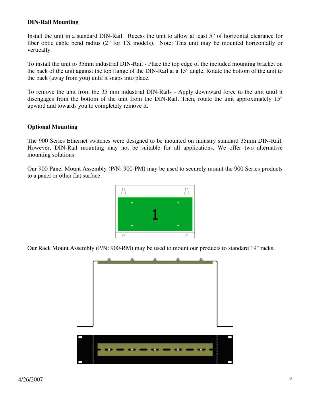
Our 900 Panel Mount Assembly (P/N: 900-PM) may be used to securely mount the 900 Series products to a panel or other flat surface.
Our Rack Mount Assembly (P/N: 900-RM) may be used to mount our products to standard 19" racks.

