N-Tron 900 manual N-Tron Switch Grounding Techniques

Models: 900

1 18
Download 18 pages 10.95 Kb
Page 14
Image 14
N-TRON SWITCH GROUNDING TECHNIQUES

N-TRON SWITCH GROUNDING TECHNIQUES

The grounding philosophy of any control system is an integral part of the design. N-Tron switches are designed to be grounded, but the user has been given the flexibility to float the switch when required. The best noise immunity and emissions (i.e. CE) are obtained when the N-Tron switch chassis is connected to earth ground via a drain wire. Some N-Tron switches have metal din-rail brackets that can ground the switch if the din-rail is grounded. In some cases, N-Tron switches with metal brackets can be supplied with optional plastic brackets if isolation is required.

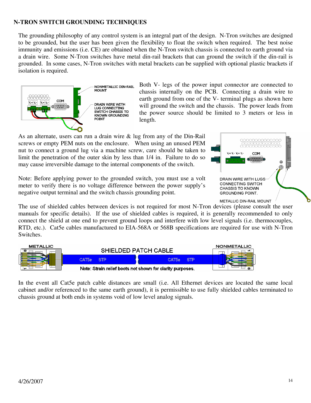
Both V- legs of the power input connector are connected to chassis internally on the PCB. Connecting a drain wire to earth ground from one of the V- terminal plugs as shown here will ground the switch and the chassis. The power leads from the power source should be limited to 3 meters or less in length.

As an alternate, users can run a drain wire & lug from any of the Din-Rail screws or empty PEM nuts on the enclosure. When using an unused PEM nut to connect a ground lug via a machine screw, care should be taken to limit the penetration of the outer skin by less than 1/4 in. Failure to do so may cause irreversible damage to the internal components of the switch.

Note: Before applying power to the grounded switch, you must use a volt meter to verify there is no voltage difference between the power supply’s negative output terminal and the switch chassis grounding point.

The use of shielded cables between devices is not required for most N-Tron devices (please consult the user manuals for specific details). If the use of shielded cables is required, it is generally recommended to only connect the shield at one end to prevent ground loops and interfere with low level signals (i.e. thermocouples, RTD, etc.). Cat5e cables manufactured to EIA-568A or 568B specifications are required for use with N-Tron Switches.

In the event all Cat5e patch cable distances are small (i.e. All Ethernet devices are located the same local cabinet and/or referenced to the same earth ground), it is permissible to use fully shielded cables terminated to chassis ground at both ends in systems void of low level analog signals.

4/26/2007

14

Page 14
Image 14
N-Tron 900 manual N-Tron Switch Grounding Techniques