Nady Systems UHF24 Link 4 PLUG-IN Transmitter, Receiver Volume Controls Adjust, Level Trim Adjust

Models: UHF24HT1112 UHF24

1 8
Download 8 pages 40.48 Kb
Page 5
Image 5

LINK 4™ PLUG-IN TRANSMITTER

Receiver Volume Controls Adjust

The volume controls work only for the 1⁄4” sum output. Turn Volume controls on the UHF-24 receiver clockwise to near full gain. Adjust Volume up or down so that no audio distortion is present when amplifi er or mixer is set at their usual levels. At full gain, the system gain is approximately +20dB higher than a direct line-to-amp connection.

If the fi xed level XLR OUTPUTS (11) are used, the volume level of each receiver should be ad- justed by the mixer to which the UHF-24 receiver is connected.

Level Trim Adjust

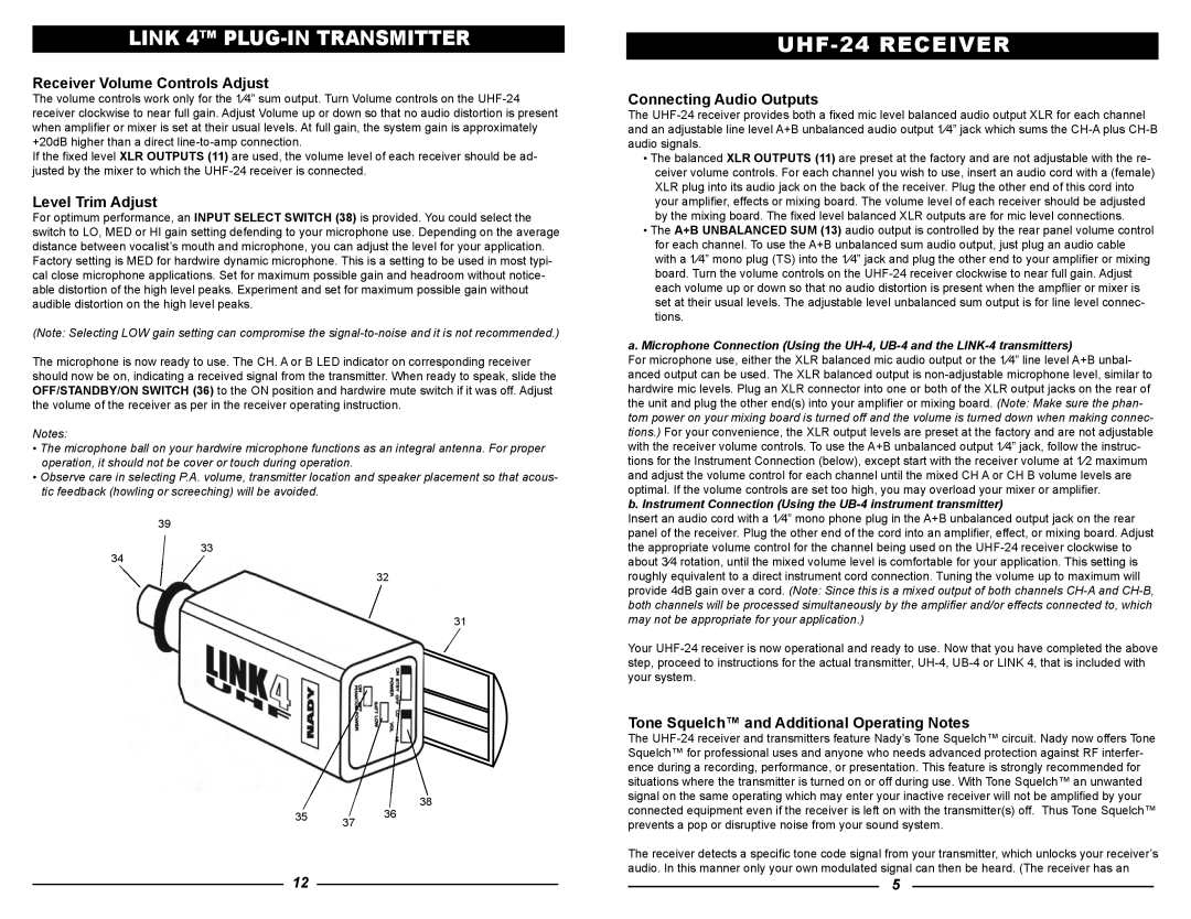
For optimum performance, an INPUT SELECT SWITCH (38) is provided. You could select the switch to LO, MED or HI gain setting defending to your microphone use. Depending on the average distance between vocalist’s mouth and microphone, you can adjust the level for your application. Factory setting is MED for hardwire dynamic microphone. This is a setting to be used in most typi- cal close microphone applications. Set for maximum possible gain and headroom without notice- able distortion of the high level peaks. Experiment and set for maximum possible gain without audible distortion on the high level peaks.

(Note: Selecting LOW gain setting can compromise the signal-to-noise and it is not recommended.)

The microphone is now ready to use. The CH. A or B LED indicator on corresponding receiver should now be on, indicating a received signal from the transmitter. When ready to speak, slide the OFF/STANDBY/ON SWITCH (36) to the ON position and hardwire mute switch if it was off. Adjust the volume of the receiver as per in the receiver operating instruction.

Notes:

The microphone ball on your hardwire microphone functions as an integral antenna. For proper operation, it should not be cover or touch during operation.

Observe care in selecting P.A. volume, transmitter location and speaker placement so that acous- tic feedback (howling or screeching) will be avoided.

39

33

34

31


38

35

36


37

UHF-24 RECEIVER

Connecting Audio Outputs

The UHF-24 receiver provides both a fi xed mic level balanced audio output XLR for each channel and an adjustable line level A+B unbalanced audio output 1⁄4” jack which sums the CH-A plus CH-B audio signals.

The balanced XLR OUTPUTS (11) are preset at the factory and are not adjustable with the re- ceiver volume controls. For each channel you wish to use, insert an audio cord with a (female) XLR plug into its audio jack on the back of the receiver. Plug the other end of this cord into your amplifi er, effects or mixing board. The volume level of each receiver should be adjusted by the mixing board. The fi xed level balanced XLR outputs are for mic level connections.

The A+B UNBALANCED SUM (13) audio output is controlled by the rear panel volume control for each channel. To use the A+B unbalanced sum audio output, just plug an audio cable with a 1⁄4” mono plug (TS) into the 1⁄4” jack and plug the other end to your amplifier or mixing board. Turn the volume controls on the UHF-24 receiver clockwise to near full gain. Adjust each volume up or down so that no audio distortion is present when the ampflier or mixer is set at their usual levels. The adjustable level unbalanced sum output is for line level connec- tions.

a.Microphone Connection (Using the UH-4, UB-4 and the LINK-4 transmitters)

For microphone use, either the XLR balanced mic audio output or the 1⁄4” line level A+B unbal- anced output can be used. The XLR balanced output is non-adjustable microphone level, similar to hardwire mic levels. Plug an XLR connector into one or both of the XLR output jacks on the rear of the unit and plug the other end(s) into your amplifi er or mixing board. (Note: Make sure the phan- tom power on your mixing board is turned off and the volume is turned down when making connec- tions.) For your convenience, the XLR output levels are preset at the factory and are not adjustable with the receiver volume controls. To use the A+B unbalanced output 1⁄4” jack, follow the instruc- tions for the Instrument Connection (below), except start with the receiver volume at 1⁄2 maximum and adjust the volume control for each channel until the mixed CH A or CH B volume levels are optimal. If the volume controls are set too high, you may overload your mixer or amplifier.

b. Instrument Connection (Using the UB-4 instrument transmitter)

Insert an audio cord with a 1⁄4” mono phone plug in the A+B unbalanced output jack on the rear panel of the receiver. Plug the other end of the cord into an amplifi er, effect, or mixing board. Adjust the appropriate volume control for the channel being used on the UHF-24 receiver clockwise to about 3⁄4 rotation, until the mixed volume level is comfortable for your application. This setting is roughly equivalent to a direct instrument cord connection. Tuning the volume up to maximum will provide 4dB gain over a cord. (Note: Since this is a mixed output of both channels CH-A and CH-B, both channels will be processed simultaneously by the amplifi er and/or effects connected to, which may not be appropriate for your application.)

Your UHF-24 receiver is now operational and ready to use. Now that you have completed the above step, proceed to instructions for the actual transmitter, UH-4, UB-4 or LINK 4, that is included with your system.

Tone Squelch™ and Additional Operating Notes

The UHF-24 receiver and transmitters feature Nady’s Tone Squelch™ circuit. Nady now offers Tone Squelch™ for professional uses and anyone who needs advanced protection against RF interfer- ence during a recording, performance, or presentation. This feature is strongly recommended for situations where the transmitter is turned on or off during use. With Tone Squelch™ an unwanted signal on the same operating which may enter your inactive receiver will not be amplified by your connected equipment even if the receiver is left on with the transmitter(s) off. Thus Tone Squelch™ prevents a pop or disruptive noise from your sound system.

The receiver detects a specifi c tone code signal from your transmitter, which unlocks your receiver’s audio. In this manner only your own modulated signal can then be heard. (The receiver has an

12

5

Page 5
Image 5
Nady Systems UHF24HT1112 owner manual Link 4 PLUG-IN Transmitter, Receiver Volume Controls Adjust, Level Trim Adjust